


A SWASH-PLATE ENGINE.
Page 32
If you've noticed an error in this article please click here to report it so we can fix it.
A Résumé of Recently Published Patents.
Swash-plate mechanism has a peculiar fascination of its own for the mechanically inclined; when it is applied to the construction of an automobile engine its interest covers a wider fie/d. Such an engine is described, with that fullness and wealth of detail which is a characteristic oi American specifications, in,patent No, 170,019, by D. D. J.Ohnston. He-niakes the awash-plate, or wabbler, as he calla it, do duty as a crankshaft, thereby attaining a most compact construction for an eleven-cylinder engine. It may be advisable first of all, to explain what is meant by a awash-plate or wabbler, since certainly not every reader of The Commercial Motor will understand the meaning of the term. We 'propose to describe it, not in general, but as it is applied in this particular case. The, cylinders of this eleven-cylinder • engine he side by side, in a ring round the engine shaft, to which they are parallel ; that is to say, the axis of each cylinder lies parallel with that of the engine shaft. itself. To the shaft is keyed a comparatively small disc; this disc does not, however, lie at right angles to the shaft, but is inclined to that position at an angle of, in this instance, 26 degpees. This disc is called the awash-plate or wabbler head; it/ actually serves as a bearing upon which is mounted the awash-plate itself. The latter is really a substantial ring, from which project eleven radial rods, these rods being provided, at a suitable point in the length of each, with spherical projections to which the connecting rods in the cylinders are attached. The other ends of the connecting rods are also attached to the gudgeon pins by spherical joints, so that the movement of the connecting rods is not constrained in any way except as regards the direction of their length.
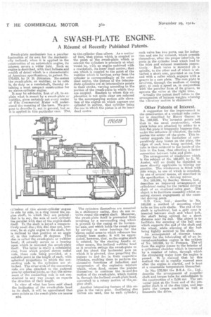
In view of what has been•said about the inclination of the awash-plate head to its shaft, it will be appreCiated that some points on the awash-plate are nearer B34 to the-cylinder than others. As a matter of fact, that piston which is coupled to the point of the awash-plate which is nearest the cylinders is precisely at what would be, with an engine endowed with a crankshaft, its inner dead centre; that one which is coupled to the point of the wabbler which is farthest away from the cylinder is correspondingly at its outer dead centre, the pistons of the intermediate cylinders are at intermediate points in their stroke, varying according to the portion of the awash-plate to which they are coupled. Readers to whom this explanation is not quite clear are referred to the accompanying section side elevation of the engine on which appears one cylinder in section, that cylinder being the one in which the piston is at its inner dead centre
The cylinders themselves are mounted in a stationary casing, they do not re. valve round the engine shaft. Moreover, the awash-plate itself is prevented from revolving by a surrounding ring which is pivoted to the' easing on its horizontal axis, and which holds the awash-plate by serving as outer bearings -for the "eleven radial arms to which reference has already been made; it will be appreciated, however, that, as.the.engine'shaft is rotated, by the starting handle or other means, the inclined wabbler head as it revolves swings the swath-plate to and fro about the horizontal axis on which it is pivoted, thus propelling the pistons to and fro in their respective cylinders, enabling them to perform the successive functions of induction and compression of the explosive mixture which, when fired, causes the pistons themselves to continue the to-and-fro motion of the awash-plate, which motion ia, through the inclined awash-plate head, converted to a rotary motion of theore gine shaft.
Another interesting feature of this engine is the valve gear. Oscillating disc valves are used, one to each cylinder;
each valve has two port; one for indue. non and one for exhaust, which present themselves, after the proper intervals, to ports in the cylinder head which lead to the inlet and exhaust manifolds respectively.•• Each valve is mounted on a spindle, to the other end of which is attached a short arm, provided at its free end with a roller which engages with a groove in a cam plate. The cam plate is revolved, through the medium of timing gear, at such a speed as, in conjunction with the peculiar form of its groove, to operate the valve at the right time.
• Actually the patent itself refers to the arrangement of balance weights whereby the vibratory motion is eliminated.
Other Patents of Interest.
A suggestion for the improvement in the construction of a vertical tube radiator is described by Henry Garner in No. 169,855. The inventor points out that in the usual construction when plain tubes are, attached by solder to a thin flat plate it frequently happens that, under the influence of vibration, the tube pushes the -solder off the-plate: This inventor suggests the formation of comparatively deep bosses on the plate, the edges of each boss being serrated, the tube is then soldered to the inside of the hale in the boss, thus effecting a better connection between tube and plate. The arrangement of windscreen which is the subject of No. 169,877, by L. W. Auster, will no doubt be regarded as more directly applicable to touring car practice. The windscreen is fitted with aide wings, to one of which is attached, by one of several means, all described in the specification, a driving mirror.
• No. 169,881, by Bentley Motors; Ltd., describes an improved arrangement of cylindrical casing for the vertical driving shaft of an Overhead-valve gear. The object is to facilitate assemblyewhilst ensuring Correct engagement of the essential driving gears. O.D. Cars, Ltd., describe in No. 169,888 a. method of mounting wheel hubs on live axle shafts. The end of the ahaft is cylindrical, but a split cone is inserted between shaft and wheel hub, the " shaft being sPlined for a short distance near its end. The object is to facilitate the Securing of the ball race which supports the end of the shaft and the wheel, ,while allowing of the hub being' tightly secured to the shift. An .arrangement of thermic transformer for the lubricating oil of-an internal-comhustion engine is the subject of No. 169,934, by G. •Fornsea. The oil from the engine passes to the interior of a cylindrical chamber which is traversed by a number of tubes, through which the circulating water from the engine is passed. It is claimed that by this method the oil is rapidly warmed soon after the engine-is. started, and is kept at a 'reasonable temperature thereafter.
In No.' 170,064 the B.S.A. Co., Ltd., deScribe the arrangement of propeller shaft. and torque tube for embodiment in the construction of a light car. The universal joint at the front end of the Propeller shaft is of the disc type, and supports the torque reaction as well as transmits the drive.