


SOLVING THE LOADING DELAY PROBLEM.
Page 17
If you've noticed an error in this article please click here to report it so we can fix it.
Novel Removable Wagon Body Used by the Midland Railway.
IN OUR ISSUE of 9th March, 1916, we drew attention to the novel and interesting removable wagon body which had been designed by Mr. Charles cruthrie Conradi, M.I.Mech.E., of the Chief Mechanical Engineer's Department, Midland Railway, Derby. The outstanding advantage of this invention is the provision of a simple and inexpensive means of avoiding delays arising from loading upon consignors' premises. The idea has been taken to the practical application stage, as the accompanying illustrations prove, the Midland Railway using one or two installations , in connection with their electric fleet.
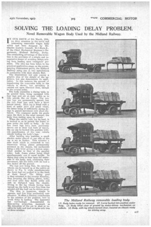
The illustrations not only convey a graphic idea of the details of the appliance, but also demonstrate its application. In this instance the process of transferring the removable body to the vehicle is shown, but unloading is carried out upon identical lines, though in the reverse order.
The body resembles a dining table in its general line.s, being equipped with four 'legs and set at ;such width as to ride astride the car frame. The tWO rear legs are permanently spaced, but the two front legs each have a short lateral travel. Each leg is fitted with a kind of ankle joint and small wheel, tho latter being of sufficiently strong design to permit movement over short distances. The consignor packs his goods upon the deck in the usual manner, the body then resting upon its wheels.
"A hen the vehicle calls for its load, it is backed so as to permit the frame to pass under the table or body. As the two front legs have been previously drawn out to their full limit of travel, the car can be backed into position without apprehension of the rear vehicle wheels fouling the body's legs.. After backing into position, a small electric motor placed on one side of the car is set, in motion. This actuates a side shaft which is, connected to two transverse lifting plates permanently mounted on the chassis, the mechanism being a side lever giving a motion somewhat similar to that of the parallel ruler, both frame plates being lifted simultaneously i.nct to equal height. In rising they Come to bear upon the underside of the body, and continuing their . movement, lift the table with its load a few inches off the ground.
The legs now being free, its carrying wheels can. be turned up at the ankles as shown in Fig. 4, while simultaimously the front legs are pushed in to the limit of their. travel. The lifting gear is then actuated in the reverse direction, thus lowering the lifting plates, body, and load until they finally settle and rest as designed upon the chassis.
Owing to the leg wheels having been turned up, the body is now free from the growid and the load can be driven away. The idea is ingenious, simple to operate, and free from mechanical com
plication. It offers a distinct contribution
to the solation of the problem, how to avoid delay: in loading. The apparatus has convincingly demonstrated its time-saving properties, inasmuch ' as the detention of the car to shed or receive its body and load occupies only two or three minutes.