


A Wheel-hub Reduction Gear
Page 62
If you've noticed an error in this article please click here to report it so we can fix it.
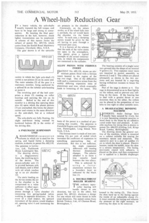
IN a heavy vehicle, the axle-shafts usually transmit the full torque, and have to be large and strong in conse quence. By locating the final gearreduction in the hub, however, much lighter transmission can be employed. A scheme of this nature forms the subject of patent No. 689,710, which comes from the Euclid Road Machinery Company, Cleveland, Ohio, U.S.A.
The gear shown is of the epicyclic
variety in which the light axle-shaft (1) carries a sun-pinion (2) on its outer end. The outer annulus (3) of the gear is a stationary member, being anchored by a splined fit on the tubular axle-housing at point 4.
The revolving part of the hub comprises a drum (5) running on roller bearings and carrying the rim on its outside. Bolted to the end of this member is a driving disc carrying three Pins (6) upon which the planet pinions (7) are journalled; this forms the planetcarrier and rotates in the same direction as the axle-shaft, but at a reduced speed.
The axle-shafts are fully floating, the slight end-thrust being resisted by hardened buttons (8) in the centre of the driving disc.
A PNEUMATIC SUSPENSION UNIT
A ROAD-VEHICLE suspension r I scheme in which air is used for the spring, and liquid forms a damping medium, is shown in patent No. 682,110. The patentee is Levita
tion, Ltd., Tackbrook Road, Leamington Spa.
The drawing shows, in a diagrammatic form, the working parts of the device. The piston-cylinder unit (1) is pivoted between axle and chassis, and is filled with oil which reaches up to an air chamber (2)_
The static loading on the device causes the air in the chamber to be compressed to a value sufficient to effect equi-, librium. The oil pipe
passes through a valve chamber (3) containing two spring-loaded valves working in opposite directions. In the event of a road impact, the upward movement of the piston would displace oil, opening valve 4 and increasing the A36
air pressure in the chamber.
Conversely, on the return stroke, or if the wheel falls into a pot-hole, the oil would leave the chamber via the lower valve. In each case, a damping action would be given by the oil having to pass through a restricted port area.
It is a feature of the scheme that the ends of the valve stems are open to the atmosphere. The patent gives a typical example of the actual construction, in which the components are contained in the cylinder.
ALLOY PISTON WITH FERROUS INSERT
PATENT No. 689,129, shows an aluminium piston fitted with a ferrous insert located in the region of the top two rings. One of the difficulties with such a construction arises from the widely differing expansion rates of aluminium and iron, which eventually ,leads to loosening of the insert. The
basis Of the patent is a method of preventing this trouble. The patentee is Fairchild Engine and Airplane Corporation, Farmingdale, Long Island, New York, U.S.A.
The ferrous insert is made of iron containing 121 per cent. of nickel which increases the coefficient of expansion to something approaching that of aluminium. But this is not sufficient, the slight expansion difference still causing thermal dimensional changes. The scheme adopted is to form a
true ' metallic bond between the two alloys. This is achieved by using a ferroaluminium mixture for a boundary layer as indicated by the black line (I).
A DOUBLE-THRUST ROLLER BEARING
THEordinary taperroller bearing will handle thrust in one direction, but not in the other, but patent No. 689,261, discloses a design for one which will resist thrust in both axial directions. The patent comes from British Timken, Ltd., 65 Cheston Road, Birmingham, 7.
The bearing consists of a single outer race ground into the shape of an internal V-groove (1). Two separate inner races are required to permit assembly, as shown at 2 and 3. The rollers are placed alternately as shown in the two sections and are located by a cage-ring having milled-out recesses to house the rollers.
Part of the cage is shown at 4. The cage is dimensioned so as to float lightly on the rollers, and so prevent any rubbing on the races. If the bearing has to deal with a greater thrust in one direction than in the other, the rollers can be placed in the proportion of two lefts to one right or other suitable ratio.
A BRAKE-FACING BONDING . MACHINE
HITHERTO, brake facings have 'usually been secured by rivets, but it is now becoming common practice to bond them to the shoes by an adhesive cured under heat and pressure. A suitable machine for doing this is shown in patent No. 686,933 (Girting, Ltd., Kings Road, Tyseley, Birmingham).
The drawing shows the general outline of the machine, which is mounted on a cabinet suitable for storing the necessary spares and materials. The operative part is a pair of saddles (I) on to which the shoe is placed. Electric heaters, inside the saddle, raise the shoe to a certain temperature. The facing, previously coated with adhesive, is placed on the shoe, and then compressed air is applied to a flexible diaphragm housed in the casing (2). This forces the shoe hard up to the facing against the inside of an adjustable clamp (3). A timer controls the curing and releases the pressure at the right moment, so allowing the shoe to be removed,