


Carburation, 3
Page 51
If you've noticed an error in this article please click here to report it so we can fix it.
THE SIMPLE carburettor is unsuitable for motor vehicle work because the mixture it produces become progressively richer as the engine speed increases, I explained this in my last article CM, March 15). So to make it suitable for use on engines operating at constantly varying speeds and loads this tendency must be ''corrected..' The word "correction" used in relation to carburettors refers to the method by which unsuitable• variation of mixture strength is prevented.
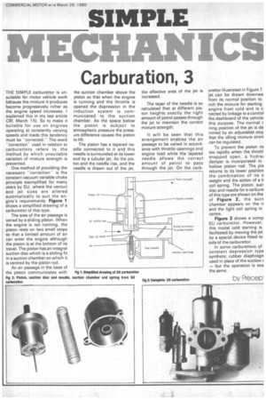
One method of providing the necessary -correction" is the constant vacuum variable choke principle exemplified for many years by SU, where the venturi and jet sizes are altered automatically to suit the engine's requirements. Figure 1 shows a simplified drawing of a carburettor of this type.
The area of the air passage is varied by a sliding piston. When the engine is not running, the piston rests on two small stops so that a limited amount of air can enter the engine although the piston is at the bottom of its travel. The piston has an integral suction disc which is a sliding fit in a suction chamber on which it is centred by the piston rod.
An air passage in the base of the piston communicates with the suction chamber above the piston so that when the engine is running and the throttle is opened the depression in the induction system is communicated to the suction chamber. As the space .below the piston is subject to atmospheric pressure the pressure difference causes the piston to lift.
The piston has a tapered needle connected to it and this needle is surrounded at its lower end by a tubular jet. As the piston and the needle rise, and the needle is drawn out of the jet,
the effective area of the jet is increased.
The taper of the needle is so calculated that at different piston heights exactly the right amount of petrol passes through the jet to maintain the correct mixture strength.
It will be seen that this arrangement enables the air passage to be varied in accordance with throttle openings and engine load while the tapered needle allows the correct amount of petrol to pass through the jet. On the carb
urettor illustrated in Figure 1 jet can be drawn downwa from its normal position to rich the mixture for starting engine from cold and is c nected by linkage to a control the dashboard of the vehicle this purpose. The normal r ning position of the jet is de mined by an adjustable stcT that the idling mixture stren can be regulated.
To prevent the piston ris too rapidly when the throttl snapped open, a hydrai damper is incorporated in hollow piston rod. The pis returns to its lower position the combination of its o weight and the action of a Ii coil spring. The piston, suci disc and needle for a carbure of this type are shown on the of Figure 2, the suet chamber appears on the ri and the light coil spring in centre.
Figure 3 shows a comp SU carburettor. However, this model cold starting is facilitated by moving the jet by a special device fitted to side of the carburettor.
In some carburettors of constant depression type synthetic rubber diaphragn used in place of the suction — but the operation is exa the same.
by Precep