


A Pre-Combustion-chamber Design
Page 60
If you've noticed an error in this article please click here to report it so we can fix it.
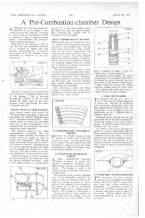
PAA DESIGN for the pre-combustion chamber of an oil engine is described in patent No. 766,233. The aims are better fuel-air intermixture which is claimed to give a quieter-running engine. (Daimler-Benz A.G., StuttgartUnterturkheim, Germany.)
Referring to the drawing, it will he seen that the pre-combustion chamber (I) is toroidal in shape and may contain a heater-plug (2). A connecting passage (3) to the cylinder creates turbulence as indicated by the two arrows (4).
The fuel is sprayed in a conical form and much of it is deposited on the wall of the passage. This is removed through the velocity of the air both during the latter part of the compression stroke and during the initial combustion period.
'IDLING WITH A COLD ENGINE AN engine needs more power for idling when cold than it does hot, and patent No. 768,323 (Daimler-Benz A.G., Stuttgart-Oriterturkheirn, • Germany) shows a scheme for providing "extra fuel in this 'circumstance. It is intended both for oil engines and those employing petrol injection.
The injection pump is very often pneumatically controlled, and the present scheme modifies the degree of • suction when an engine is cold by means of a thermostat. The drawing shows part of the intake pipe in which 1 is the main air throttle. By-passing this is a pair ofparallel passages (2) which can be brought into action by a slidevalve (3). The pipe 4 leads to the control diaphragm of the injection pump.
When the engine is hot, the passages are kept closed by the slide-valve and the throttle functions normally. With a cold engine, however, a thermostatic capsule (5) in the water-jacket moves the slide-valve into the open position, thus lowering the suction and So increasing the fuel supply.
HEAT ABSORPTION IN BRAKES THE metal parts of a brake heat very -I. rapidly in use because metals generally, have a low specific heat. On the other hand, Water has a high -specific heat; for the same temperature rise water would absorb about six times as much heat energy. Patent No. 768,279 (Goodyear. Tire and Rubber' Company, Akron, Ohio, U.S.A.) discloses a scheme for including trapped water in a brake disc to enable it to absorb much more energy before heating up.
The drawing shows a section of such a brake-disc; it is provided with numerous cells and connecting passages all of which are filledwith water. Manufacturing problems are overcome by building the brake disc up from punched sheet welded together, and two or more filling plugs are provided. .
For extra-heavy duty, the filling would: be ammonia; this absorbs more heat because of the change of state from Liquid to gas when heated. .
DAIENT No. 768,019 reveals a brake design in which both a disc and a drum are used. The disc carrier ca.n move slightly with the rotation and this movement is used to power the drum braking shoes. (Bendix Aviation Corp., South Bend, Indiana, U.S.A.) AN IMPROVED HYDRAULIC TAPPET
ASELF ADJUSTING hydraulic tappet is shown in patent No. 767,816 iThompson Products Inc., 23555 Euclid Avenue, Cleveland, Ohio, USA), The design is said to be simple, and easy to produce in commercial quantities':
The drawing shows a partly exploded view of the assembly; normally the closure collar (1) would be held in the body by a cirelip in groove 2. Compressive force applied to the bottom of the tappet by a cam is transmitted through liquid (3) to sliding ring 4 which is then closed by valve head 5.
On the upstroke a small quantity of liquid leaks past the sliding ring and thus shortens he stroke slightly. This fluid is trapped in space 6 and lifts sealing ring 7 against spring 8.
During the idle period this .Spring reclaims the lost moventent and allows the liquid to return through the now open valve to the bottom compartment. A light spring (9) 'returns the sliding ring, into contact with the valve head.
The liquid used would preferably be a high-viscosity silicone polymer.
A CAB 'VENTILATOR
TO ventilate the cab of a lorry bus is the aim of a device disclosed in patent No. 768,139 (A. Galbraith and Anemostat (Scotland), Ltd., 181 West Regent Street. Glasgow, C.2).,' By adjustment, it can be made to give an appreciable air jet, a diffused flow -or complete shut-off.
Mounted in the roof of the cab, the right-hand end of the device points forwards and scoops in air as the vehicle moves. A deflector plate (1) serves to exclude rain and snow.
The inlet to the cab is through the centre of a large sheet-metal ball (2). This is open on one side and fitted with a diffuser (3) on the other. It can be turned so as to have the diffuser inoperative at the top, or operative at the bottom as shown. By partly turning. the ball, it can be made to close the inlet completely.
AN INJECTION PUMP GOVERNOR
T.FWgovernors Of some . injection pumps have centriftigal bob-weights which, when the shaft is horizontal, may have their action modified by gravitation. A governor revealed in patent No. 769,150 is designed in such a. manner that gravity has no effect on the a ction. -(Robert. Bosch G.m.b.H., 4 Breitscheidstrasse, St u t t ear t-V)e,
Germany.) .