 1
1 2
2 3
3 4
4 5
5 6
6 7
7 8
8 9
9 10
10 11
11 12
12 13
13 14
14 15
15 16
16 17
17 18
18 19
19 20
20 21
21 22
22 23
23 24
24 25
25 26
26 27
27 28
28 29
29 30
30 31
31 32
32 33
33 34
34 35
35 36
36 37
37 38
38 39
39 40
40 41
41 42
42 43
43 44
44 45
45 46
46 47
47 48
48 49
49 50
50 51
51 52
52 53
53 54
54 55
55 56
56 57
57 58
58 59
59 60
60 61
61 62
62 63
63 64
64 65
65 66
66 67
67 68
68 69
69 70
70 71
71 72
72 73
73 74
74 75
75 76
76 77
77 78
78 79
79 80
80 81
81 82
82 83
83 84
84 85
85 86
86 87
87 88
88 89
89 90
90 91
91 92
92 93
93 94
94 95
95 96
96 97
97 98
98 99
99 100
100 101
101 102
102 103
103 104
104 105
105 106
106 107
107 108
108 109
109 110
110 111
111 112
112 113
113 114
114 115
115 116
116 117
117 118
118 119
119 120
120 121
121 122
122 123
123 124
124 125
125 126
126 127
127 128
128 129
129 130
130 131
131 132
132 133
133 134
134 135
135 136
136 137
137 138
138 139
139 140
140 141
141 142
142 143
143 144
144 145
145 146
146 147
147 148
148 149
149 150
150 151
151 152
152 153
153 154
154 155
155 156
156 157
157 158
158 159
159 160
160 161
161 162
162 163
163 164
164 A New Rubber Suspension System
Page 120
If you've noticed an error in this article please click here to report it so we can fix it.
I N various rubber suspension systems which have been tried • during the past ten years the rubber has generally been employed in compression. A recent example is found in the Scammell six-wheeler which was first exhibited at Olympia in 1-933. In contrast with such systems, the de.. signs which have been evelved by Mr. Colin Macbeth, consulting mechanical engineer to the Rubber Growers' Association, employ this resilient material in torsion.
An outstanding feature of Mr. Macbeth's patented method is that the rubber is uniformly stressed throughout, thus reducing weight to a minimum. By employing an ample margin of safety it is found possible to avoid any "settling," whilst the life of the rubber appears to be sufficient to last out the chassis. These points have been verified by laboratory tests and by trials on the road. The absence of any abrasion is another sound feature, the rubber being bonded to steel end-plates.
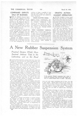
In a typical application of the uew system, each front wheel is independently supported by a parallelogram linkage resembling certain systems of independent suspension which are now quite popular for private cars. Movements of the upper link impart a turning effect to a conical endplate, which is bonded to a tubber block of considerable diameter. A similar plate at the opposite end of the block is prevented from turning by an adjustable screw.
Consequently, the downward load is resisted by the torsional stress in the block of rubber and this material provides a resilience which enables it to replace the conventional steel toad spring. Extreme movements, including rebound, are checked by auxiliary rubber units as shown in the illustration.
Mounted on a strong cross-member, in needle bearings, the linkages are built up to form a freint suspension unit which can readily be applied to a conventional chassis frame. The geometry is such as to give precise steering and a constant wheel track, so safeguarding the tyres from undue wear.
Given protection from sunlight (such as is afforded by the usual mudguard) and suitably safeguarded from oil, the rubber shOuld last indefinitely. As regards the bond between rubber and steel, prolonged experience with solid 131.4 tyres and with engine mountings goes to show that this is fully reliable. Should failure occur for any reason, the vehicle could be driven home at a slow speed, resting on the stops, whereas with a broken steel spring it is some times impossible to continue the journey. Furthermore, the rubber unit can easily be replaced after removing a single nut.
An outstanding advantage of rubber for springing is its 'dead-beat" action, which is due to the considerable amount of energy dissipated in the form of heat when the rubber is stressed. In the opinion of many authorities this should render separate shock-absorbers unnecessary. There is ample scope for heat dissipation, the rubber block being mounted in such a position as to receive adequate cooling from its motion through the air.
Mechanically, the Macbeth system appears to be sound, there being ample bearing surfaces and suitable provision for lubrication. The inventor has also applied the idea to rear suspension, using the rubber in torsion, as before, but employing a trailing linkage instead of the transverse parallelogram. It is stated that in price and weight this rubber suspension can compete with more conventional layouts.