


Coal-gas Fittings.
Page 18
If you've noticed an error in this article please click here to report it so we can fix it.
A Brief Description of a Necessary Piece of Apparatus.
In arranging to use coal-gas for internal-combustion engines from a supply which is under pressure, some device must be intOrporated in the supply pipe to reduce the pressure Of the gas. practically to equal that of the atmo,sphere, and this reducing valve, as it is ordinarily named, must be automatic in action. It must further be so designed that a regular and even supply of gas is maintained. The design of such a valve from first principles is not beyond the skill of the ordinary engineer or draughtsman.
Existing Design, of Proved Merit, Can Be Utilized Now.
Considerable advantage will accrue, however, from a study of our illustrations on this page, which show the valve employed on the Neath Tramways, where, as we pointed out in our issue of 2nd November last, coal-gas has been used for rather more than 18 years. It follows from this fact that the design of the apparatus has evolved, by means of frequent improvement based on the results of experience, from some less efficient type, though perhaps simpler. It will certainly be more economical .to copy a prgved and existing
design than to commence experimenting again ab nitzo.
The principle involved in the construction of this valve is merely that a leather diaphragm, which inflating on .pressure above the desired amount and deflating when the pressure is not reached, closes or opens, respectively, a valve in the gas supply pipe.
Detail Description.
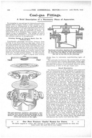
Our illustrations are of the reducing valve separated into its component parts, and drawn in perspective. For the purposes of our description, the sectional view, which we also reproduce, will perhaps be more useful. Gas enters at thepipe shown on the left, passing through a filter, reaching a small conical valve. This valve opens or closes the inlet to a chamber which, besides containing the mechanism of the device, serves also as a reservoir, for gas, containing perhaps about half a cubic foot. The exit is by ineafts of a branch pipe on the right, which branch pipe will, of course, be coupled up to the engine induction. This reservoir is covered by a leather diaphragm stiffened
in the centre by perforated brass washers. The centre of, the diaphragm is coupled by means of links and a lever to the small valve already mentioned. Reference to the drawing will go further than any verbal explanation in presenting the details of this device to our readers. It will be seen that a light spring rests on the top of the leather diaphragm, and this spring is adjustable for strength by means of a screw. The object of any regulation of the pressure exerted by the spring is to enable various gas pressures to. be maintained, and to obviate difficulties which might arise otherwise owing to frictional resistance of the mechanism. A flat spring shown held lightly at one end by a bracket in the base of the chamber tends always to closo the valve. It will be gathered that, the excess of pressure above that desired will tend to lift the leather diaphragm, and close the valve; so soon, however, as the pressure in the chamber, drops below that which it is desired to maintain, then., the spring above the _diaphragm will depress the leather and open the valve.