 1
1 2
2 3
3 4
4 5
5 6
6 7
7 8
8 9
9 10
10 11
11 12
12 13
13 14
14 15
15 16
16 17
17 18
18 19
19 20
20 21
21 22
22 23
23 24
24 25
25 26
26 27
27 28
28 29
29 30
30 31
31 32
32 33
33 34
34 35
35 36
36 37
37 38
38 39
39 40
40 41
41 42
42 43
43 44
44 45
45 46
46 47
47 48
48 49
49 50
50 51
51 52
52 53
53 54
54 55
55 56
56 57
57 58
58 59
59 60
60 61
61 62
62 63
63 64
64 65
65 66
66 67
67 68
68 69
69 70
70 71
71 72
72 73
73 74
74 75
75 76
76 77
77 78
78 79
79 80
80 81
81 82
82 83
83 84
84 85
85 86
86 87
87 88
88 89
89 90
90 91
91 92
92 93
93 94
94 95
95 96
96 97
97 98
98 99
99 100
100 101
101 102
102 103
103 104
104 105
105 106
106 107
107 108
108 109
109 110
110 111
111 112
112 113
113 114
114 115
115 116
116 117
117 118
118 119
119 120
120 121
121 122
122 123
123 124
124 125
125 126
126 127
127 128
128 129
129 130
130 131
131 132
132 133
133 134
134 135
135 136
136 137
137 138
138 139
139 140
140 141
141 142
142 143
143 144
144 Shaking Mechanism for a Tipping Body
Page 100
If you've noticed an error in this article please click here to report it so we can fix it.
TIPPING bodies used for carrying 1 sticky material, such as clay, often fait to discharge theirload completely, even when tipped to maximumangle. The driver's favourite remedy is to shake the vehicle by use of the clutch
and brakes, a practice that can be very harmful to the transmission.
Patent No. 747,201 (K. Thistlethwaite and Pilot Works, Ltd., Manchester Road, Bolton, Lanes) shows a hydraulic tipper fitted with a pulsating valve that shakes the body hydraulically.
The drawing shows the construction of the valve, which is connected at end 1 to the end-of-stroke release valve of the ram. Two connections (2 and 3) are included in the pipe between pump and ram, whilst the release ports (4) are open to the reservoir.
When the knock-off valve is opened, the oil is admitted to the cylinder (5) and moves a piston (6) to the left. An extension on the piston strikes a closed cone-valve (7) and opens it; this vents the pump circuit to the release ports and causes an immediate pressure drop. The cone-valve is then re-closed by its spring as the oil escapes from a calibrated leak (8).
The whole of this action is cyclic and so imparts a shaking action to the body, the preferred frequency being about 200 cycles per minute.
LIGHTER TORSION BARS
FROM J. Harnott and The Austin Motor Co., Ltd., Longbridge Works, Birmingham, comes patent No. 748,587, describing improvements in torsion bars for suspension systems. The object is to achieve lightness by eliminating useless metal.
In a torsion bar, the part near the outer skin provides most of the resit ence, the centre portion contributing but little. In the present scheme there is no centre part, the bar being a nested assembly of thin tubes.
The drawing shows an exploded view of an assembly. Three concentric tubes (1) are used, each of which B14 consists of a pair of semi-circular sectors. They are assembled so that the longitudinal edges are vertical on the inner and outer tubes, but horizontal in the middle one.
Slots (2) on the end are used to form an anchorage when assembled on a keypiece (3), the whole being gripped on to a central plug (4) by a split clamp (5). The surfaces of the tubes are preferably subjected to a skin-stressing treatment to improve their strength. The friction between the various tubes provides a useful damping action.
BETTER ACCESSIBILITY FOR MASTER CYLINDERS
THE master cylinder of a hydraulic braking system is often placed low down under the bonnet where it is not only awkward to get to, but also collects mud and dust. Patent No. 746,357 (Ford Motor Co., Ltd., 88 Regent
Street, London, W.1), deals with a cylinder mounted high up on the dash and fitted with a transparent reservoir through which the liquid level can be seen.
The main part of the cylinder is cast in metal, but above it is a screwed-in transparent reservoir (1). This, being in a clean location, enables the level to be inspected merely by lifting the bonnet. Should the plastic reservoir be accidentally broken, the brake is not put out of action because the metal neck (2) is made large enough to hold sufficient working fluid.
USING THE FLOOR AS A HOT-AIR DUCT
FROM Fiat Societa Per Azioni, Turin, Italy, comes patent No, 747,158, which discloses a novel use for the floor of a chassisless
vehicle. Although described as applied to a car, its use is not limited to this.
The floor of the vehicle is strengthened for the purpose of acting as the frame for the attachment of the various components. T h e strengthening is made in thc form of a box-girder which acts also as a duct for hot air.
A diagonal girder (1) receives the hot air from the engine radiator (2) and conveys it to the centre of the floor where it joins a central girder (3). After traversing this, the air is fed into an up-duct (4) which terminates in a fan shaped nozzle (5). This acts as a windscreen de-mister. Lower apertures (6) may be provided to blow out warm • air at foot level. A control-valve is fitted at this point for shutting off the air.
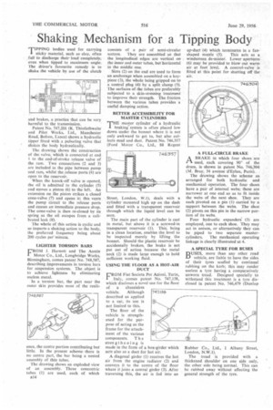
A FULL-CIRCLE BRAKE
ABRAKE in which four shoes are used, each covering 90° of the drum, is shown in patent No. 746,304' (M_ Bray, 34 avenue d'Eylau, Paris).
The &awing shows the scheme as. arranged for both hydraulic and mechanical operation. The four shoes have a pair of internal webs; these are narrower at one end so as to fit inside. the webs of the next shoe. They are each pivoted on a pin (1) carried by a support between the webs. The shoe (2) pivots on this pin in the narrow portion of its webs.
Four hydraulic expanders' (3) are employed, one to each shoe. They may act in unison, or alternatively they can be piped to two separate master cylinders. The mechanical operating linkage is clearly, illustrated at 4.
A SPECIAL TYRE FOR BUSES
BUSES, more than any. other road vehicle, are liable to have the sides of their tyres scuffed by continual rubbing on the kerb; this may render useless a tyre having a comparatively unworn tread. Designed specially to withstand this treatment is a tyre disclosed in patent No. 746,479 (Dunlop
Rubber Co., Ltd., 1 Albany Street, London, N.W.1).
The tread is provided with a thickened shoulder on one side only, the other side being normal. This can be rubbed away without affecting the general strength of the tyre.