 1
1 2
2 3
3 4
4 5
5 6
6 7
7 8
8 9
9 10
10 11
11 12
12 13
13 14
14 15
15 16
16 17
17 18
18 19
19 20
20 21
21 22
22 23
23 24
24 25
25 26
26 27
27 28
28 29
29 30
30 31
31 32
32 33
33 34
34 35
35 36
36 37
37 38
38 39
39 40
40 41
41 42
42 43
43 44
44 45
45 46
46 47
47 48
48 49
49 50
50 51
51 52
52 53
53 54
54 55
55 56
56 57
57 58
58 59
59 60
60 61
61 62
62 63
63 64
64 65
65 66
66 67
67 68
68 69
69 70
70 71
71 72
72 73
73 74
74 75
75 76
76 77
77 78
78 79
79 80
80 81
81 82
82 83
83 84
84 85
85 86
86 87
87 88
88 89
89 90
90 91
91 92
92 93
93 94
94 95
95 96
96 97
97 98
98 99
99 100
100 101
101 102
102 103
103 104
104 105
105 106
106 107
107 108
108 109
109 110
110 111
111 112
112 113
113 114
114 115
115 116
116 117
117 118
118 119
119 120
120 121
121 122
122 123
123 124
124 125
125 126
126 127
127 128
128 129
129 130
130 131
131 132
132 133
133 134
134 135
135 136
136 137
137 138
138 139
139 140
140 A Petrol-injection Device
Page 106
If you've noticed an error in this article please click here to report it so we can fix it.
THE growing popularity of petrol injection calls for a suitable metering means, and such a unit is shown in patent No. 653,030, by C.A.V. Ltd., Warple Way, London, W.3. The device described is a variable-output distributor, and has to be supplied with a constant supply of petrol under pressure from a separate pump.
Referring to the drawing, the fuel under pressure arrives at an annular space (1) surrounding a rotary ported sleeve-valve (2) driven in timed relationship with the engine. Inside the valve is a free plunger (3) which can slide between a fixed stop (4) and an adjustable one (5). The adjustable stop forms the quantity control, and functions by limiting the amount of space for the free plunger to slide in. The position of the stop is subject to a combination of manual control via lever 6 and intake suction acting on a diaphragm (7).
In operation, the rotary valve controls fuel-pressure to first one end of the free plunger and then to the other, thus forcing one charge of fuel out of each of the pipe-lines (8) in turn. This action, although readily controllable by the adjustable stop, is completely unaffected by any variation of the pressure of the fuel supply.
A BUILT-IN SPRAG
T0 start a vehicle on a steep up-hill grade calls for careful co-ordination of clutch, throttle and brake controls and it is not always that drivers make
a clean start in these circumstances. A device to help the operation is shown in patent No. 652,913, by A. Lea, 70, Cranford Road, Coventry.
In this scheme, a one-way lock is built into the transmission so that the vehicle cannot run backwards. The lock is interconnected with the gear-selecting mechanism so that the action of engag ing reverse gear automatically throws the lock also into the reverse position.
In the drawing, 1 is the output shaft of the gearbox. To it is keyed an annular drum (2) containing the locking mechanism. This consists of a free-wheel in which rollers (3), journalled on a spring-centred carrier plate (4), are trapped between the drum and member 5 on which there are three flats.
By rocking this member one way or the other, the direction of locking is aJtered, and by coupling this movement to the gear-selector, the a c t i on becomes automatic. As shown, the selector is arranged to turn the quick-threaded screw (6) via a lever fixed to shaft 7.
A LIFTING SYSTEM FOR CONTAINERS
CONTA1NERS which can be transferred in a loaded slate from one vehicle to another are covered in patent
No. 653,145. The patentee, J. Jennings, "Three Ways," Sandbach, Cheshire, describes a simple lifting scheme for onor off-loading such containers to or from the vehicle.
The container is fitted with four brackets (1) to which can be attached a set of outriggers (2); these are simply hooked on in the vertical position, and swung outwards as shown. The unloading station would be equipped with a set of jacks (3) or a block-and-tackle for attachment to rings (4). Once lifted from the vehicle, the container could be stood on trestles (5) until required.
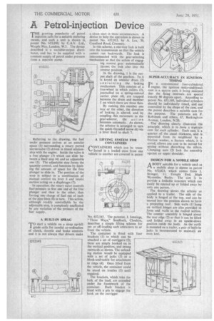
The brackets, which take the bulk of the load, are extended under the framework of the container. Each bracket is fitted with a pin to engage the hook on the outrigger. SUPER-ACCURACY IN IGNITION TIMING IN a conventional four-cylindered engine, the ignition make-and-break cam is a square unit; it being assumed that the firing intervals are spaced exactly 90 degrees apart. According to patent No. 653,169, individual cylinders should be individually timed, and not controlled by the shape of the cam, and the patent describes a suitable cam for the purpose. The patentees are F. Robinson and others, 67, Buckingham Avenue, London, N.20.
The drawing clearly illustrates the principle, which is to have a separate cam for each cylinder. Each cam is a quarter of the usual thickness, and is separated from its neighbour by a friction washer, a feature which, it is stated, allows one cam to be moved for setting without disturbing the others. Clamping nuts (2) lock the assembly against an upper shoulder.
DESIGN FOR A MOBILE SHOP
ABODY suitable for a vehicle used as a mobile shop is shown in patent No. 652,823, which comes from J. Stringer, 11, Temple End, High Wycombe, Bucks. The aim is to provide a foldable structure which can easily be opened up or folded away by only one person.
The drawing shows the scheme as applied to a trailer. The side of the body is hinged at the top, and can be moved into the position shown to-form a projecting roof. Side walls (1) hung on vertical hinges are also provided to form end walls to the roofed section. The counter assembly is hinged about the rear edge 12) so that it can be lifted and folded away in an upside-down position inside the body. As the outfit is mounted on a trailer, a pair of built-in jacks is incorporated to maintain an even keel.