


FIRST DETAILS OF NEW aS 7.58-LITRE OIL ENGINE
Page 26
Page 27
Page 28
If you've noticed an error in this article please click here to report it so we can fix it.
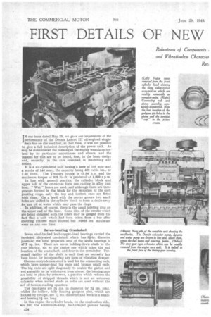
IN our issue dated May 25., we gave our impressions. of the performance of the Dennis Lancet III oil-engined single deck bus on the road but, at that time, it was not possible to give a full technical description of the power unit. As may be remeMbered the running of the engine was charactericed by its particular smoothness and silence, and the reasons for this are to be found, first, in the basic design and, secondly, in the care exercised in machining and fitting.
it is a six-cylindered unit having a bore of 150 inm.• and a stroke of 146 mm., the capacity being 462 cubic ins., or 7.58 litres. The Treasary rating is 41.04 h.p. and the maximum torque of 335 lb.-ft. is produced•at 1,000 r.p.m.
In line with general practice, the cylinder block and upper half of the crankcase form one casting in alloy cast iron. " Wet " liners are used, and although there are three grooves formed in the block for the reception of the cork jointing rings, only the top and bottom ones are fitted with rings. On a Level with the centre groove two small holes are drilled in the cylinder block to form a drain-away for any oil or water which may pass the rings.
In addition, of course, there is the usual jointing ring on the upper end of the liner. Some idea of the results which are being obtained with the liners may be ganged from the fact that a unit which had been taken from a bus after covering 175,000 miles showed but .01035 ins maximum wear on any one liner.
Seven-bearing Crankshaft Seven steel-backed lead-copper-lined bearings carried the hardened alloy-steel crankshaft which has al-in. diameter journals; the total projected area of the seven bearings is 47,7 sq. ins. There are seven, holding-down studs to the rear bearing, six to the centre one which takes the end location of the crankshaft, and four to the remainder, Torsional rigidityof the shaft is such that no necessity has been found for incorporating any form of vibration damper.
Chrome-molybdenum steel is used for the connecting rods, which have copper-lead big ends and bronze small ends. The big ends are split diagonally to enable the piston and rod assembly to be withdrawn from above; the bearing caps
are held in place by setscrews, a practice which reduces the possibility of 'stripped threads which is not in unknown calamity when nutted studs or bolts are usedwithout the aid of torsion-reading spanners..
The crankpins are 3' ins, in diameter by 2i ins, long,' whilst the hollow, fully floating gudgeon pins, which are located by circlips, are li ins. diametecand Work in a smallend bearing 11 ins. long.
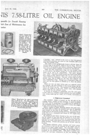
In this engine the cylinder heads, on the combustion side, are flat, the aluminium-alloy, heat-treated pistons having A24 ,
a toroidal " cup " formed in the clown so that the primary combustion processes are more or less localized well away from the cylinder walls.
The centre of the gudgeon-pin bosses is 21 ins. from the bottom edge of the piston, which is 61-36. ins. long. This low location of the gudgeon pin follows customary Dennis practice, and good piston stability is claimed for this feature.
There are four compression rings and two scraper ring; to each piston, the former being in. on the faces and the latter A in. and in. respectively. The A-in. scraper is a" solid" ring and is fitted around the base of the piston skirt which is fully relieved below the ring in order to prevent a build-up of pressure. The 1-in. scraper ring is of the slotted type, and is fitted in the ring land beneath the four compression rings. Wedge-type compression rings are used and the first groove is formed in. from the piston crown.
There are two air, inlet valves and two exhaust valves per cylinder, the port diameter of the former being 'Tag ins. and of the latter 1116 ins. The material of which the inlet valves are made is 3 per cent. nickel steel, with chrome silicon steel for the exhaust valves.
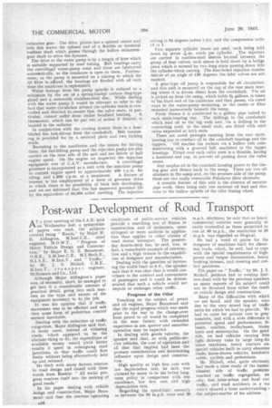
A feature of interest in connection with the valve gear is that there is a complete rocker assembly for each cylinder and, ,being made up as a unit, it is readily removable as such.
A High-levef Camshaft
The camshaft, which is located on the off side of the cylinder block, carried in four bearings, is made in chilled cast iron, and by mounting it at a high level in relation to the crankshaft centre line it is possible to reduce the weight of the valve-operating mechanism.
• hollow tappets of large diameter operate the push rods, the lower ends of which are rounded and bear in spherical cups formed in the base of the tappets. By locating the thrust point at the lowest possible level the angula4ity of the push rods is at a minimum and thrust on the tappet sides is also reduced.
An all-helical gear train, located at the rear of the unit, has its wheels in cast iron and the pinions in .6 per cent. carbon steel, a combination which, in conjunction with the helically cut teeth, gives good wear-resisting properties and silent running. Wheels and pinions are all l ins, wide on the face.
The Dennis exhauster pump, dynamo and water pump are mounted in line on the nearside of the engine and are driven at l times engine speed. The exhauster, which is bolted on to the timing-gear housing, has its helical pinion mounted on the primary shaft. This shaft is hollow and carries one spur-gear component of the two farming the
exhauSter gear. The drive pinion has a splined centre and into this mates the splined end of a flexible or torsional resilient shaft which passes through the hollow exhaustergear shaft to drive the dynamo.
The drive to the water pump is by a length of hose which. is suitably supported by steel tubing. Ball bearings carry
the centrifugal water-pump rotor and these are lubricated autontatically, as the crankcase is open to them. Furthermore, as the pump is mounted on a casting to which the all filter is affixed, the bearings are flooded With oil 'each time the crankcase is replenished.
Water leakage from the pump spindle -is reduced to a minimum by the use of a spring-loaded carbon ring-type gland and a renewable stainless-steel disc. While dealing with the water pump it would be relevant to refer to the fact that water circulation around the cylinder heads is con trolled and directed to ensure that the valve seats, hi par ticular, cannot suffer from undue localized heating. A thermostat, which can be put out, of action if desired, is located in the radiator. • In conjunction with the cooling system there is a fourbladed fan belt-driven from the crankshaft. Belt tensioning is provided for by a serrated plate and two locking studs.
Reverting to the auxiliaries and the means for driving them, the fuel-lifting pump and the injection pump are also carried on the near side of the unit and are driven at half engine speed. On the engine we inspected the injection equipment was of C.A.V. manufacture. A centrifugal governor is incorporated as a unit with the injection pump to control engine speed to approximately 400 r.p.m. for idling, and 1,800 r.p.m. as a maximum. A feature of interest is the employment of a form of governor drive in which there is no possibility of back lash •developing, and we are informed that this has improved governor life by the equivalent of 80,000 miles' running. The injection setting is 34 degrees before ecl.c. and the compression ratio 15 to 1.
Two separate cylinder heads are used, each being held down by seven -76-in, studs per cylinder. The injectors are carried in rustless-steel sleeves located between the group of four valves; each sleeve is held down by a bridge piece which is secured by two long studs passing down into the cylinder-block casting. The four-holed injection nozzles deliver at an angle of 120 degrees: the inlet valves are not masked.
A gear-type oil pump is responsible for oil circulation, and this unit is mounted on the cap of the rear main bearing where it is driven direct from the crankshaft. The oil is picked up from the sum, which holds 3i gallons, is taken to the front end of the crankcase and then passes, via cored ways in the water-pump mounting, to the cooler or filter mounted transversely beneath the sump.
From thence it is conducted to a gallery pipe bolted to each main-bearing cap. The drillings in the crankshaft which lead oil to the big ends and, via a drilling in the connecting rods; to the small ends, are fitted with steel tubes expanded at both ends.
There are cored passages running from the rear mainbearing cap to conduct oil to the camshaft bearings and the
tappets. Oil reaches the rockers via a hollow bolt comrnunieating with a grooved belt machined in the tappet housings. Fitted over each valVe stem is a thimble, having a hardened end cap, to prevent oil passing down the valve stems.
Any surplus oil in the camshaft housing passes to the timing gear and thence back to the sump. There are two oil strainers in the sump and, on the pressure side of the pump, there are two easily removable Purolator filter elements.
A. notable feature of this unit is the absence of exterior pipe work, there being only one external oil lead and that runs to the hollow spindle of the idler timing wheel.