


Self-energizing Disc-type Brake
Page 72
If you've noticed an error in this article please click here to report it so we can fix it.
A Resume of Recently Published Patent Specifications Obtain4le from the Patent Office, Price !s. Each
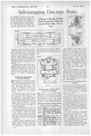
A BRAKE in which the usual shoe and drum assembly is replaced by an end-moving disc system forms the subject of patent No 520,279 by A. Girling and others, Guildhall Buildings, Navigation Street, Birmingham. In the drawing the rotating part comprises the wheel hub (4) carrying a spoked member (3) which is freely splined at its outer edge to the fabricfaced Central disc (1). A stationary disc (2) is fixed to a Part of the axlecasing (7), and forms the adjustable member, being backed by a screwed ring (5). This ring is fitted with gearteeth, and these can be turned for adjustment by means of a pinion-ended tool (6) which is inserted for the purpose.
In operation, the second disc (9) is pressed to the right, thus firmly gripping the friction disc. Disc 9 is backed by a number of steel balls (8) trapped in conical holes, and their efforts to ride up the sides of the h'clprovide a valuable self-energizing effect.
PNEUMATIC-SUSPENSION CONTROL SYSTEM
RECENTLY we described in patent No. 519,877 the general lay-out of a pneumatic suspension system by Firestone Tyre and Rubber Co., Ltd., Great West Road, Brentford. This concern now discloses, in patent No. 520,222, more details of the resilient bellows employed in the previous scheme.
The drawing shows, in full lines, the device in its contracted position, whilst the chain-line view illustrates its expanded state. The bellows itself is made of rubber reinforced with cotton, and the interior is lined with inner-tube rubber to prevent leakage. The air supply, from a reservoir, is controlled by a valve operated by a loosely suspended pendulum (1).
While the pendulum is at rest in its normal position, the valve is open, and the working pressure is the same as that in the reservoir. When the vehicle rounds a corner, however, the pendulums on one side of the vehicle move outwardly, and in doing so close the valves and " harden " the suspension on that side.
Another valve is arranged to discharge air quickly from the bellows, but to obstruct its re-entry, thus preventing rebound. A third valve, called an "inertia valve," comes into opera tion only during an excessive " bump " and by closing the bellows exit, prevents the rubber member from bottoming.
SWASH-PLATE ENGINE WITH ROTATING PISTONS
AN engine of the horizontally opposed, dght-cylindered swash plate type forms the subject of paten No. 517,625 by R. Watts, 30, Tinwel Road, Stamford, Lincs. This engin is stated to be an improvement on on shown in an earlier patent, No. 450,972.
The cylinders are arranged in two opposite blocks of four, and a double crank is used, the inclined portions of which are set at SO degrees to the main journals. Each of the pistons has an inclined face (2) from which a pivot pin (3) projects. These pins pass through bosses in short connecting rods (1) the other ends of which are pivoted on a sleeve (4) jounaalled on the crankpin, the assembly somewhat resembling a " swastika " in shape. This construction means that the pistons must rotate with respect to their cylinders.
The valve arrangements are normal. operation being by means of overhead camshafts (6) driven by skewgearing from the main crankshaft (5) which projects through the cylinder heads. The engine operates on the four-stroke cycle, the cylinders firing in opposed pairs simultaneously.
CLUTCH-PLATE TO GIVE GENTLE TAKE-UP
I-1 A CLUTCH plate claimed to give a smooth and gradual engagement is shown in patent No. 250,406 by BorgWarner Corp., 310, South Michigan Avenue, Chicago, U.S.A. At the same time, the component is relatively simple to produce.
The improvements lie in the construction of the central steel portion of the friction-faced disc. This is cut into spokes which are set out of the fiat in two directions, one being a direct bend from the original plane, and the other an individual twist to each spoke. As the plate is gripped for engagement, the twists are first straightened out, after which the bends• are gradually brought into the flat, giving full engagement.
As a result there is a very gradual application of the friction, affording a smooth take-up of the drive. The patentee claims that this method enables a clutch to be " tailored " to suit a particular vehicle, the only variation needed being an adjustment of the values of twist and bend.
The specification describes and illustrates a number of variations of method in bending and setting the spokes,