


MULTI-WHEELED CHASSIS.
Page 46
If you've noticed an error in this article please click here to report it so we can fix it.
A Résumé of Recently Published Patents.
If we except one or two patented designs, of which little has been heard or read beyond the patent specification, and apart from compound vehicles, like the Knox or the Scamme11, we are justified in stating that the motor vehicle is generally conceived as a four-wheeled one. Any exception to the rule inclines to a diminution of the number of wheels
rather than an increase: if anything comes of the invention of L. E. de Mole, however, we are in for a radical change, for, if its advantages are to be realized at, all, then the chassis which embodies it must have a number of aides with a comparatively small distance .between each. As a matter of fact,' however, the claims which appear in thesspecification, which is numbered. 143,006, are; all in connection with a "read vehicle having at least four pairs of wheels."
Apart jrom. the number of wheels and axles, the. important feature of the de,
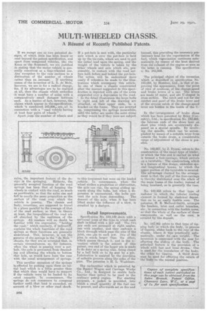
sign is the springing. Hitherto, the generally accepted function of the road springs has been that of keeping the wheels in contact with the road, as much as practicable, so that the axles rise and fall in nearly the same proportion as the seirface of the road over which the vehicle is passing. The chassis and body, meantime are supposed to travel in a plane parallel to the avexage of that of the road surface, so that, in theory at least, the inequalities,ef the road are all absorbed by the resilience of the springs. All readers will no doubt be familiar with the expression, "holdineg the read," which concisely, if indirectlY, explains the whole functions of the road springs as those functions are generally undertood. This, however, is not the purpose of tite,springs in the "do Mole" chassis, for they are so arranged that, in certain circumstances, as, for instance, vihen the wheel is passing over a pothole, the axle is prevented Timm descending and allowing the wheels to bottom that bole, as would have been the case with the usual arrangement of 7springs.
This peculiar operation of the springs is.effected by putting upon them an initial load which is a little greater than that which they would have to support if the vehicle were to be loaded to its rated capacity. In consequence, the springs do not commence to compress further until, that load is exceeded, on account of a blow or other road shock. If a pot-hole is met with, the particular axle which is over the pot-bole is held up by the tie-rods, which are used to put the initial load upon the spring, and the weight of the vehicle is taken by the 'other wheels and axle which are, presumably, in contact, with the road sur• face both before and behind the pot-hole. The action will be understood more easily if reference be made to the illustrations which accompany this Reticle. In one of them a chassis constructed after the manner suggested in this specification is depleted with one of the axles suspended over a depression in the road. ' In the detail illustration the 'large bolts to right an left .of the drawing are attached, at their upper ends, to a bracket on the frame. They are screwed up, compressing the springs meanwhile until the latter are under the same stress as they would be if they were not subject
to this treatment but were on the loaded i,vehicle. Iii consequence, when the "wheel strikes a projection or obstruction, the axle can rise, the spring sliding upwards along the bolts, but when EL depression is encountered, the bolts pre
vent the axle from descending. The descent of the axle, when it has been lifted under the influence of a blow, ia steadied by a dashpot.
Detail Improvements.
Specification No. 143,149 deals' with a universal -joint of the type in which each shaft ise fitted with a jaw end. The two jaw ends are arranged at right .angles, one with another, and they embrace a block through which pars the pins of the joint, one pin to each jaw. One of the pins is much larger than the other, which passes through it, and in the htvention which is the subject of • this patent, one end of the larger pin is made to do duty as a spring oiler, being closed by a ball held on to its seat by a pin. Lubrication is assisted by the provision of suitable grooves along the sides Of the pins. The patentee is H. L. Washburn.
The carburetter which is patented by the Bristol Wagon and Carriage Works Co., Ltd., is designed to enable feels heavier than petrol to be used in the
ordinary petrol engine. For starting purposes, a jacket is provided, into which a small quantity of the fuel can be poured, and afterwards set On fire and burned, this providing the necessary preliminary heat for the vaporization of the fuel, which vaporization continues auto-. matically by reason of the heat derived from the exhaust of the engine En soon ar the latter is running. The specification ia No. 143,059..
The principal object of the invention which s described in specification No.' 143,054, by Humber, Ltd., is tint of improving the appearance, from thepoint of view of neatness, of the change-speed and brake levers of a, car. The levers are made Of metal, and are TI-shaped in cross-section. The catch and rod for the ratchet and pawl of the brake lever and' of the reverse catch of the change-speed• lever are hidden in the inside of the In thee arrangeme»t of brake &mos which has been patented by Riley (Coventry}, Ltd., in specification No. 143,005, the fulcrum ends of the shoes bear on. short pins which are eccentrically dieposed on a special spindle. By revolv-e ing the spindle, which can be acoom-: plished by means of a suitable lever from; outside. the brake drum, a considerable range of -adjustment of the shoes is pos
.
sible.
No. 142,957, by J. Dyson, refers to the' construction of the usual type of trailer, . ire which the fore end is carried on what is termed a. fore-carriage, which swivels on a turntable.The construction. which is a feature of this design, embodies special longitudinal Learns, towhich the. upper portion of the turntable is secuted. The advantage claimed for the arrangement is that the pull of the fore-carriage is thereby distributed over the whole of the main frame of the trailer, instead of being localized, as is generally the 'Case.
No. -142,933 refers to that type -of radiator 'in which, the tubular Cooling element is formed by electrical deposition on to an easily fusible core. The patentee, H. R. Melland-Smith, arranges the headers, inlet and. outlet branches, etc., in connection with the fusible gores, So that .the Whole of the surface of these components, 'as well as the core'; is' tiover'ed by the.deposit,
No. 142,962 refees•to that typo of tipping body' in 'which the .hody, in process of tipping, slides back. to the rear of the chassis, where it tips practically automatically, under its mien weight. The invention is concerned with the gear for effecting the sliding of. the body. The principal feature is the' provision of • a . winch with fast and loose drums. One is used ,for.the translation of the body; the other for tipping. A third drum may be used for effecting the return of the body to the nomad: position.