


Abridgments of Interesting Patent Specifications.
Page 16
If you've noticed an error in this article please click here to report it so we can fix it.
No. x6,/it, dated July 20th, 1904 A. Carolan, 83, Cannon Street, London, of the General Electric Co., U.S.A.-This invention comprises a variable stroke mechanism for feeding water to a boiler or liquid fuel to a burner in a motor velnole, though it may he used for other purposes. On suitable supports fro) on the vehicle a frame (ii) is mounted. On opposite sides of the frame bearings (13) are provided to receive the trunnions (14), which are secured to and carry the flanged adjustable guides or supports (s5). The guides or supports are provided with rect. angular slots (16), having straight edges, which are arranged to receive the sliding blocks (x7), the latter being connected to the driving mechanism. One of the
grooves is arranged to receive one block, while the other groove is arranged to receive the block on the opposite side. The adjustable guides or supports (15) are connected together at the right-hand end by the pin 481, which also acts as a nut for the adjusting screw (19). In order to ensure corresponding movements of the levers or supports (15) they are connected by a U-shaped cover (20), which cover also carries ait oil cup (el) by means of which the parts can be lubricated. In the present instance a two-part guide or support (i5) is provided because the strain on the parts can be better distributed, but it is within the scope of the invention to use only a single guide or support. In order to vary the effective stroke of the apparatus as a .whole, it is necessary to provide means for .adjusting the position of the guide or .support 051. Such an adjusting device is found in the screw (xg), which is Itiounted in a rocking holder (22). The holder (22) is provided with trunnion-like .supports (23), the latter being carried by bearings (24), which are a part of the main frame (xi). The holder is held in fixed position on the screw by means of a collar and the nut 125). By rotating the screw in one direction or the other the holder (22) will move U p or down and the position-of the guides (15) be changed, that is to say, the guides and the connecting piece (20) swing around the trunnion (14) as a centre. Between the end of the adjusting screw and the actuating rod (26) is a universal joint (27) ,t0 compensate for differences in alignmerit between the controlling handle and the regulator.
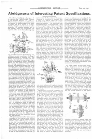
The pump piston or other driven part is connected. by-the link (3o) with the bellcrank lever (31). In the present instance both the water and fuel pumps are driven by the link (30), so that the amounts of water and fuel delivered thereby are .correspondingIy and proportionately varied_ The rods (28) are connected to the water pump and the rod (29) with the fuel pump. The rods are connected by a cross-head, and the latter is connected to the link (30), so that as the movement of the lever (31) varies so also do the strokes of the pumps. The lever or rocker (3t) is provided with a pivot (32), which enters the bosses formed in the main frame (II), and is supported thereby. The bell-crank lever or rocking device is provided with a pair of jaws or guides (331, which are arranged to receive the sliding block (34). The blocks (iv), and the block (34) which is placed between them, are pivotally connected by the same stud or shaft (35;. It is to be noted that the pivot (35), in addition to connecting the three blocks, also forms the attaching means between the blocks and the fork (36), the latter being connected to the eccentric through suitable means, such as a rod. The arms of the fork are disposed one on each side of the central block (34), and the space between the iides of the fork is somewhat greater than the width of the jaws of the bell-crank lever (3t) and also the block (341. By reason of this construction the jaws are free to move between the arms of the fork. The relation of the side and centre blocks with respect to the guides and the jaws is hest shown in Fig. 5. It is to be observed that the guide (15) and lever (3t) are pivoted to the frame (II) in such manner that they extend toward each other and overlap to a certain extent. This overlapping of the guide and lever per
enits me to reduce their length, to simplify the adjustable connection between them, and also to reduce the size of the regulator as a'whole.
The eccentric causes the connecting rod to move back and forth with a constant stroke, hence the fork (36) must move likewise. As the fork moves it carries with it the side blocks ([7) and the central block (341. When the centre block (3.0 is compelled to move with the fork (36) under the action of the eccentric, it will, when moved inward, cause the lower arm of the bell-crank lever to move in the direction of the arrow, because as the blocks move to the left the side blocks (57) drop lower and lower, owing to the downward inclination of the guides (15), until the complete movement has been made. The pivoted guide (151 is normally held in fixed relation by the screw 49) when thes anparatus is working, and it it only by changing the adjustment of this screw that the stroke of the pump can be varied. As the side blocks (17) and the centre blocks (34) move to the right under the return stroke of the eccentric the lower arm of the bell-crank lever (31) will move in the direction of the dotted arrow. This is due to the fact that the blocks are now travelling up the inclined guides (i6) or up the side of a wedge. As the blocks move back and forth this action is repeated. When it becomes necessary for any reason to change the adjustment of the pump or pumps in order to cause it or them to deliver more or less liquid, the screw (N) is adjusted from the seat of the vehicle by means of the hand wheel. In case it is desirable to decrease the amount of liquid delivered, the rod (26) and screw (19; are rotated in a direction 'to depress the right-hand end of the guide arms (15). The more nearly parallel the guides (1.6) and the surface of the jaws (33) become, the less will be the stroke of the pump or pumps, because the difference in elevation between one end of the guide (16) and the other becomes less and less until, finally, when all of the parts are in parallel relation, the blocks are free to incive to and fro without imparting any oscillating movement to the bell-crank lever, and hence the pump or pumps will be at a standstill. By reason of the fact that the guides and the jaws in the bell-crank kvet can be brought into parallel relation, the action of the pump or pumps can be entirely stopped without in any way affecting or retarding the operation of the eccentric. A further advantage of my improved construction resides in the fact that the work done by the eccentric varies with the amount of work done by the pump or pumps, that is to say, when the pump is doing full work so also is the eccentric, but as the effective discharge ofthe pomp or pumps decreases from the maximum to the minimum so also will the work performed by the eccentric be reduced from maximum to a minimum.
No. 1,149, dated January 20th, i9o5 F. W. Itedgeland, United States.--The object of this invention is to provide a substitute for differential gear in motcr vehicles. The road wheel driving axle (6) is provided at opposite ends with rightand left-handed screw-thrEaded portions (23). On these threaded portions are mounted clutch discs (21) (shown on a larger scale in Fig. 2), and beyond the same the axle is journalled, as shown at so, to receive the road wheels (5). Each wheel carries a friction plate (13) having an annular flange (18), to which is bolted a second plate (z9), situated on the opposide side of the clutch disc (21). Packing (27), or any ether convenient friction device, is provided at the ends ofthe axle casing (8), so that the clutch members (21.) will be moved endwise on the screw• threaded portions to engage either the plates 13 or to, according to the direction in which the shaft (6) is rotated. The plates (13) are preferably engaged for forward driving, and the plates (19) for rearward driving, and it will he seen that when turning a corner the wheel which overruns the axle will automatically disengage the clutch disc and rim freely, as required.