


THE CLARKSON STEAM WAGON.
Page 22
If you've noticed an error in this article please click here to report it so we can fix it.
A Résumé of Recently Published Patent Specifications.
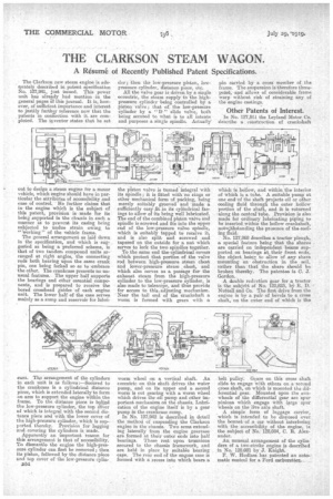
The Clarkson new steam engine is adequately described in patent specification No. 127,941, just issued. This power unit has already had mention in the general pages of this journal. It is, however, of sufficient importance and interest to justify further reference now that the patents in connection with it are completed. The inventor states that he set
out to design a steam engine for a motor vehicle, which engine should have in particular the attributes of accessibility and ease of control. He further claims that in the engine which is the subject of this patent, provision is• made for its being supported in the chassis in such a manner as to prevent, its casing being subjected to undue strain owing to "'working" of the vehicle frame. The general arrangement as laid down in the specification, and which is suggested as being a preferred scheme, is that of two tandem compound units arranged at right angles, the connecting rods both bearing upon the same crank pin, one being forked so as to embrace the other. The crankcase presents no unusual features. The upper half supports the bearings and other essential components, and is prepared to receive the bored crosshead guides of each engine unit. The lower half of the case serves mainly as a sump and reservoir for lubri
cant. The arrangement of the cylinders in each unit is as follows :—Secured to the crankcase is a cylindrical distance piece, which is extended laterally to form an arm to support the engine within the frame. To the distance piece is b
the low-pressure cylinder, the top c5Ver of which is integral with the second distance piece and with the lower cover of the high-pressure cylinder, -which is supported thereby. Provision for lagging and covering the cylinders is made. Apparently an important reason for this arrangement is that of accessibility. To dismantle the engine the high-pressure cylinder can first he removed; then its piston, followed by the distance piece and top cover of the low-pressure cylin
D54 der ; then the low-pressure piston, lowpressure cylinder, distance piece, etc. All the valve gear is driven by a single eccentric, the steam supply to the highpressure cylinder being controlled by a piston valve ; that of the low-pressure cylinder by a "D " slide valve, both being secured to what is to all intents and purposes a single spindle. Actually"
the piston valve is turned integral with its spindle; it, is fitted with no rings or other mechanical form -of packing, being merely suitably grooved and made a sufficiently easy ,fit in its cylindrical facings to allow of its being well lubricated. The end of the combined piston valve and spindle is screwed and fits into the upper end of the low-pressure valve spindle, which is suitably tapped to receive it, and is also split and screwed and tapered on the outside for a nut which serves to lock the two spindles together.
To the same end the cylindrical covers which protect that portion of the valve rod between high-pressure steam chest and lower-pressure steam , chest, and which also serves as a passage for the exhaust steam from the high-pressure cylinder to the low-pressure cylinder, is also made to telescope, and thus provide for access to this, adjusting mechanism. Near the tail and of the crankshaft a worm is formed with gears with a worm wheel on a vertical shaft. An eccentric on this shaft drives the water pump, and on its upper end a second worm is cut gearing with a worm wheel which drives the ail pump and other 1.131portant mechanism on the chassis. Lubrication of the engine itself is by a gear pump in the crankca.se sump.
In No. 12:7,942 is described in detail the method of suspending the Clarkson engine in the chassis. Two arms extending laterally from the engine gearease are formed at. their outer ends into half bearings. These rest upon trunnions secured to the chugs framework, and are held in place by suitable bearing caps. The rear end of the engine case is formed with a recess into which bears a
pin carried by a cross member of the frame. The suspension is therefore threepoint, and allows of considerable frame warp without risk of straining any of the engine castings.
Other Patents of Interest.
In No. 127,811 the Leyland Motor Co. elescribe a construction of crankshaft which is hollow, and within the interior of Which is a tube. A suitable pump at one end of the shaft projects oil or other cooling fluid through the outer hollow portion of the shaft, and it is returned 'along the central tube. Provision is also made for ordinary lubricating piping to be inserted within the hollow crankshaft, notwithstanding the presence of the codling fluid.
No. 12:7,968 describes a tractor plough, a special feature being that the shares are carried on independent beams supported on bearings at, their front ends, the abject being to allow of any share mounting an obstruction in the soil, rather than that the share should be broken thereby. The patentee is C. J. Gordon.
A double reduction gear for a tractor is the subject of No. 122,823, by H. D. Nuttall and Co. The first drive from the engine is by a pair of bevels to a cross shaft, on the outer end of which is the
belt pulley. Gears on this cross shaft slide to engage with others on a second cross shaft, on which is mounted the differential gear. Mounted upon the ssnwheels of the differential gear are spur pinions which engage with large spur wheels on the live axle shaft.
A simple form of luggage carrier, which is intended to be disposed over the bonnet of a car without interfering with the accessibility of the engine, is, the subject of No. 128,084, C. R. Alexander.
An unusual arrangement of the cylin ders of a, two-stroke engine is described in No. 128,081 by J. Knight.
F. W. Hudlass has patented an automatic control for a Ford carburetter.