


Patents Completed.
Page 18
If you've noticed an error in this article please click here to report it so we can fix it.
Complete specifications of the following patents will be sant to any address in the United Kingdom upon receipt of eightpence per copy at the Sales Branch, Patent Office, Holborn, W.C.
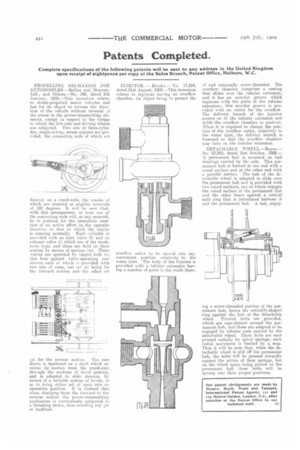
PROPELLING MECHANISM FOR AUTOMOBILES.—Belliss and Morcom. Ltd., and Others—No, 346, dated 6th January, 1909.—This invention relates to steam-propelled motor vehicles and has for its object to reverse the direction of the vehicle without reversal af the stress in the power-transmitting elements, except in respect to the torque to which the live axle and driving wheels are subjected. Two sets of three-cylinder, single-acting, steam engines are provided, the connecting rods of which act
directly on a crank-axle, the cranks uf which are situated at angular intervals of 120 degrees. It will he seen that, with this arrangement, at least one of the connecting rods will, at any momen1., be in position for the immediate exertion of an active effort in the opposite direction to that in which the enOre Is running normally. Each cylinder is provided with an inlet valve (h) arid an exhaust valve (i) which are of the mushroom type, and these are held on their seating by means of springs isn). These valves are operated by tappet rods (a) that bear against valve-operating earn sleeves each of whieh is provided with two sets of cams, one set (o) being for the forward motion and the other set
us) for the reverse motion. The cam sleeve is feathered on a shaft which receives its '.motion from the crank-axle through the medium of bevel gearing, and is adapted to slide thereon, by means of a suitable system of levers, so as to bring either set of cams into an operative position. It is claimed that when changing from the forward to the reverse motion the power-transmitting mechanism is continuously subjected to a thrusting strain, thus avoiding any jar or backlash. INJECTOR. — Brooke,— No. 17.604, dated 21st August, 1908.—This invention relates to injectors having an overflow chamber, its object being to permit the overflow outlet to be moved into any convenient position relatively to the water inlet. The body of the injector is provided with a tubular extension having a number of ports in the walls there of and externally screw-threaded. The overflow chamber comprises a casting that slides over the tubular extension, and it has an annular groove which registers with the ports in the tubular extension; this annular groove is provided with an outlet for the overflow. The delivery branch of the injector screws on to the tubular extension and holds the overflow chamber in position. When it is required to change the position of the overflow outlet, relatively to the water inlet, the delivery branch is loosened so that the overflow chamber may turn on the tubular extension.
DETACH A 13I,E WHEEL .—Royce. No. 25,252, dated 31st October, 1908.A permanent hub is mounted on ball bearings carried by the axle. This permaitent hub is formed at one end with a coned surface and at the other end with a parallel surface. The hub of the detachable wheel is adapted to slide over the permanent hub and is provided with two coned surfaces, one of which engages the coned surface of the permanent hub and the other bears against a conical split ring that is introduced between it and the permanent hub. A nut, engag ing a screw-threaded portion of the permanent hub, forces the conically-shaped ring against the hub of the detachable wheel. Pivoted bolts are provided, which are equi-distant around the permanent hub, and these are adapted to be engaged by tubular nuts carried by the detachable wheel. These bolts are each pressed radially by spiral springs ; such radial movement is limited by a stop. Thus it will be seen that, when the detachable wheel is slid off the permanent hub, the bolts will be pressed inwardly against the action of their springs, but on the wheel again being placed on the permanent hub these bolts will be sprung into their proper positions.