


MAKING BEST USE OF THE FORD.
Page 13
If you've noticed an error in this article please click here to report it so we can fix it.
Valuable Advice on Every Phase of Ford Transport, which will Appeal to the Owner, Driver, and Repairer.
IN THIS series of hints concerning the Ford light chasSis and ton truck wherever they are employed for commercial purposes, we endeavour to deal with the subject from every view-point, so that the advice given will appeal to the owner, driver, maintenance engineer' or mechanic. Valuable sources of information are being tapped for this purpose, and it should be understood that the advice given will be derived from those with an. intimate knowledge of the subject.
We shall welcome for inclusion among the hints those which have proved of value to individual users, and will make suitable remuneration for any published. What we desire are the results of practice.
162.—Misfiring Caused by End Play on the Camshaft.
A trouble recently experienced with the engine of a Ford van took the form of occasional missing, which gradually developed to a complete cutting out of the No. 3 cylinder. The coils were changed over, but were found to be quite satisfactory, and, finally, blame was thrown upon the commutator or timer, but nothing .wrong could be seen with this, and the trouble still occurred even when a spare commutator casing was employed.
As the vehicle at the time the trouble was worst was some distance from the garage, the driver tried to run home with the engine firing on three cylinders, but No. 4 then developed a miss, and another stop had to be made for inspection.
Finally, it was discovered that the brush holder of the tinier, which was of Runbaken make, had been rubbing on the back of the commutator. We hasten to add that it was not the fault of the timer, which is a make usually giving very excellent results. The cause was wear on the bearings of the camshaft, which had the effect of permitting the shaft to move outwards about in.
The trouble was how to maintain the crankshaft in its proper position. To do this a small hole was bored in the centre of the commutator casing to take a 2-in. French nail, which was pushed through the hole until it rested firmly in its centre pophole in the end of the crankshaft. It was then cut off to such a length that, with the bar holding the commutator in position, the nail just rested lightly against the camshaft and prevented any endwise movement. This proved a satisfactory arrangement and lasted until the engine was overhauled.
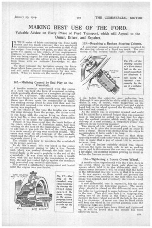
163.—Repairing a Broken Steering Column.
4 ins, below the epicyclic gear reduction box. Although it was possible to drive with it in this condition it was, of course, very dangerous, as the anchorage of the steering was partly lost and a righthand lock on the wheel opened the throttle, whilst a left-hand lock closed it.
As the vehicle was in constant demand and could not be spared for a moment longer than was essential (and to this must be added the fact that five days was the earliest premise which could be given for delivery of a new column), a temporary repair was effected in the following manner.
Two pieces of 1-in. mild steel plate, 8 ins, long, were cut to fit over the fractured part in order to form a clamp. Holes were drilled down the edges to accommodate 10 bolts, each 1 in. long. The plate edges were not bent so that those opposing touched each other when on the column, but were so made that a gap of about 1-32 in. occurred between them.
A strip of leather suitably drilled was placed between the faces on each side to act as packing pieces, and in this manner the van was run for nearly a fortnight, the steering column proving as sound as before the fracture occurred.
164.—Tightening a Loose Crown Wheel.
A trouble often experienced with the 7-cwt. Ford is the crown wheel in the back axle shearing the screws which hold it to the differential case. In almost every instance it will be found that the holes in the differential case are worn, so that it is useless to fit new screws, as these would not prevent the crown wheel from moving on the case when the foot brake was applied, and eventually the trouble would occur again. A new differential case is expensive, but the cost cart be saved in the following manner. The crown wheel should be placed on the differential case, and the holes in it arranged to come between the old ones in the case. Then drill one hole in. tapping size, using one of the holes in the wheel as a guide. Remove the bevel wheel and drill the hole in the case to in. clearance. A screw can then be fitted which will keep the wheel in the correct position until the remaining hobs are drilled. When new screws have been fitted and tightened up, it will be found that the trouble has been effectively cured.