


TEMPERATURE-CONTROLLED FAN DRIVE
Page 56
If you've noticed an error in this article please click here to report it so we can fix it.
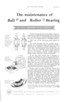
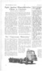
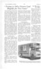
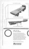
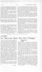
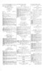
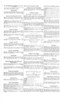
AHYDRAULIC coupling for incorporation in the drive of a fan is disclosed in patent No. 876,609. Its purpose is to maintain a constant cooling-water temperature. (Serck Radiators, Ltd., Warwick Road, Birmingham, 11.)
The coupling* is a pump of the gear type and can be adjusted to transmit any torque between free and fully locked.
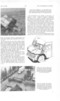
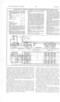
In the drawing, a central gear (1) meshes with two free planet pinions (2 and 3) to form the pump. The fan is mounted on the central gear spindle (4) and the opposite spindle (5) is the input member, driving the gear housing.
In operation, the circulating oil is led through a bore (6) containing a piston valve spring-biased to the open position. A temperature-responsive capsule, also in the bore, is immersed in cooling water taken through a branch pipe, The action is that as the temperature of the water rises from cold, the fan-drive is gradually brought up to speed as the oil flow is obstructed by the closing valve.
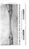
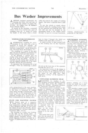
PLATE FOR MAGNETIC CLUTCH
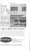
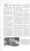
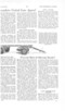
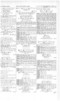
THE friction discs of a magnetic clutch must be able to withstand high temperature without distortion and a plate designed with this in view forms the subject of patent No, 876,594. (Eaton Manufacturing Co., 739 East 140th Street, Cleveland, Ohio, U.S.A.)
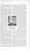
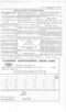
The drawing is a scrap view looking at the edge of the moving plate. It consists of a disc (1) mounted for ;axial sliding against retracting springs. The actual engaging surface is created by a number of segmental pads (2). These arc si2 bent to form V-shaped ribs which are welded to the main disc at points 3.
A radial air-flow is thus created both on the working face via the V-grooves (4) and on the back face of the segments through the spaces (5).
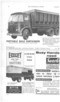
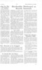
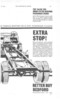
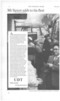
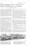
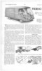
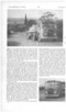
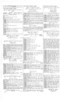
An important feature of the design is that the main disc is dished to allow he centre of mass of the segments to lie in the plane of the slide pins. This eliminates " coning " of the segments at high speed, CONTAINER HANDLING GEAR AECHANISM for loading or disal charging containers between ground and body level forms the subject of patent No. 876,098. (Dempster Brothers Inc., Knoxville, Tennessee, U.S.A.) The drawing shows a container on the ground in readiness for loading. The vehicle carries a tipping frame operated conventionally by a hydraulic ram (I).
Inside the frame is a second ram which, when extended, engages a hooked member with the container at the point (2). The ram is then retracted and hauls the container up the slope for approximately a quarter of its length. Locking devices then hold the container while the ram returns for a second pail. This operation is repeated until the container is fully in place on the frame. The tipping ram then returns it to the horizontal.
The patent then goes fully into the details of the scheme and contains 21 drawings.
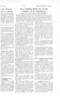
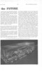
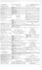
LOW-TENSION IGNITION A CCORDING to patent N, r-k a low-tension high-currere will fire with certainty mixtur• over-rich or otherwise unl without causing fouling of the ignition system of this type subject of the patent. (Globe-1 900 East Keefe Avenue, 1 Wisconsin, U.S.A.)
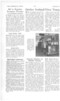
The circuit shown in the dia, prises a conventional battery complete with contact breaker limiting resistor (3). This eni primary winding of a tomb former (4) which has a gap magnetic circuit to increase 1 energy.
The secondary output circui1 in series, a germanium rectifier storage capacitor (7). In oper capacitor is alternately charge rectifier and discharged across points (8). The switching is by a second contact assembly
The E.M.F. across the sparki only of the order of 1,000 volt discharge current may be as hi amps. The discharge occurs in one micro-second or less.