


POPPET t_ 1 - 1
Page 38
Page 39
If you've noticed an error in this article please click here to report it so we can fix it.
e_r evolution
VALVES and shortcomings THi, modern petrol engine has passed through many stages in its evolution, and, although the general arrangement and outward shape of its component parts may not appear to have undergone a marked change, the vast advance in reliability and the output obtainable from a given capacity, indicate that, as a. whole, great strides have been made.
Cylinders, crankshafts, pistons and connecting rods have undoubtedly undergone much detailed revision, but the factor having, perhaps, a bearing greater than any other upon the successful evolution of the power unit, has been the improvement brought about in the region of the • valve and its operating mechanism.
The poppet valve has been assailed at various stages in its history by other forms of mechanism, but with, perhaps, one exception it now occupies practically the whole field. It does not follow from this that it possesses all the advantages and no disadvantages, but the fact that it can be designed to operate for long periods under trying conditions has stood it in good stead. There are cer tam n faults which have not yet been eliminated, and a résumé of its development and shortcomings may not be out of place.
In the early days speeds, compressions and temperatures were low ; valves were actually made from mild-steel forgings which gave fairly good service. Later, when designers set out to obtain higher output, these factors rose to levels demanding better valve material.
The troubles arising were manifold and concerned the burning of the valve face where it touches the seating, and the burning and scaling of the neck. Prominent also was the question of the elongation of the neck, under the combined stress of heat and increased spring pressure—made necessary to compel the tappet to follow the cant profile at speed ; further, there was the unreliability brought about by the failure of the ordinary cotter arrangement.
In order to overcome these difficulties a vast amount of experimental work had to be undertaken, efforts being made to find an alloy better able to withstand the burning action or to incorporate a steel stem with a close-grained, cast-iron head ; the latter material is reasonably efficient in combating the destructive ravages of heat. Eventually the solid valve won on this point when suitable alloy steels were brought into being.
A factor in the burning of the face portion was traced to the seating in the block being insufficiently cooled. As this also burnt away the water-passage, the question had to be thoroughly studied in order to remove the cause.
Further research upon combustionhead design enabled still higher speeds to be accomplished, which, in turn, called for greater spring pressures, and then came the trouble of hammered faces, elongated necks and broken cotter holes, together with occasional 4.4 burnouts."
Hammered faces took the form of deep rings or imprints of the cylinder seating in the valve face itself, and the elongated necks and broken cotter holes appeared with annoying regularity.
The reason for all these troubles was that, up to this stage, the metallurgists bad tackled the material problem upon a basis of adding nickel to the steel. Although this practice gave an alloy capable of fairly .satisfactorily combating the heat problem, it also resulted in a valve of insufficient Brinell hardness at the higher temperatures, involving, in addition to the troubles mentioned, the hammering of carbon particles into the face, which brought about a "gas blow" and the ultimate burning of the valve.
All these difficulties were eventually overcome, however, by the designers and metallurgists working hand in hand, non-scaling and non-burning alloys being produced which would operate at the required temperature whilst preserving the requisite amount of hardness and mechanical strength. This was accomplished by adding tungsten, chromium and other ingredients to the valve material, and the redesigning of the method of retaining the valve collar and spring by the incorporation of a split collar or similar arrangement.
At the same time other matters of a more mechanical nature had to be Tackled, as stroboscopic observation showed that the valve bounced upon the seating. This involved an intensive study of cam profiles and tappet mechanism, Certain troubles are still with us. ror example, valves must be ground (-old, and they cannot be expected to preserve exactly the same shape when raised several hundred degrees in temperature. Also, a wearing action takes place on the stems, owing to their being difficult to lubricate. These gradually wear, along with the guides, allowing The mixture to be upset by air being drawn up the inlet guides and, what is worse, preventing an accurate seating of the valves,
The screwdriver slot in the head by no means contributes to the regular expansion necessary for gas-tightness, and it seems that this device will have to go, although suction methods, which are not considered by everyone to be so convenient for grinding purposes, have, in some such arrangements, to be resorted to.
Long experience has shown that lubri eating thimbles considerably assist in mitigating stem and guide wear. More attention is now being paid to the desirability of enclosing the whole of the valve gear and allowing oily vapour to have free access to the valve guides. This system is bound to give longer life and higher efficiency.
Despite the progress which has been made--and it is considerable—it is necessary to ensure greater reliability of the valve gear and to minimize the amount of attention which must be paid to it. With commercial vehicles traversing big distances annually the need is obvious.
Amongst the special instances of progress in valve and valve-gear design is that of the Ford A-type engine, which forms the power unit of the whole range of commercial vehicles and motorcars as now listed.
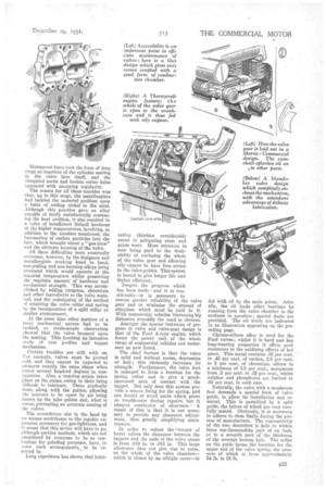
The chief feature is that the valve is solid and without recess, depression or hole ; this obviously increases its strength. Furthermore, the valve foot is enlarged to form a location for the spring collar and to give a muchincreased area of contact with the tappet. Not only does this system provide a secure fixing for the spring, and one devoid of small parts which prove so troublesome during repairs, but it ensures continuity of clearance. ' A result of this is that it is not necessary to provide any clearance adjustment, thus greatly simplifying maintenance.
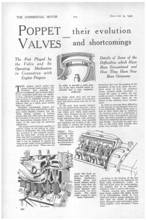
In order to reduce the 'danger of burnt valves the clearance between the tappets and the ends of the valve stems is from .010 in. to .013 in. This large allowance does not give rise to noise, as the whole of the valve chamber— which is closed by an °Might cover—is fed with oil by the main pump. Actually, the oil feeds other bearings by running from the valve chamber to the surfaces in question ; special ducts are provided. The oil levels are indicated in an illustration appearing on the preceding page.
Chrome-silicon alloy is used for the Ford valves ; whilst it is hard and has long-wearing properties it offers good resistance to the oxidizing effects of hot gases. This metal contains .35 per cent. to .45 per cent, of carbon, 2.8 per cent. to 3 per cent, of chromium, silicon to a minimum of 3.8 per cent., manganese from .2 per cent. to .35 per cent., whilst sulphur and phosphorus are limited -to .02 per cent, in each case.
Naturally, the valve with a mushroom foot demands a special form of valve guide, to allow its installation and removal. This is permitted by a split guide, the halves of which are very carefully mated. Obviously, it is necessary to adhere to close limits during the process of manufacture. The concentricity of the two diameters is held to within three ten-thousandths part of an inch, or to a seventh part of the ..thickness of the average human hair. The collar on the guide forms the location for the upper end, of the valve spring, the pressure of which is from approximately 34 lb. to 38 lb.