


MOTOR OMNIBUS SPRINGING.
Page 28
If you've noticed an error in this article please click here to report it so we can fix it.
A Résumé of Recently Published Patents.
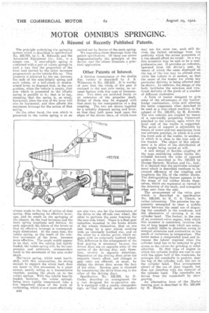
The principle underlying the springing system which is described in specification No. 182,724, by C. K. Edwards and the Associated Equipment Co., Ltd., is a simple one. A -spring is cOmbined with a pair of volute springs in such a way that the proportion of the total load carried by the latter increases progressively as the vehicle fills up. This property is achieved by the use, between the ends of the semi-elliptic spring and each volute, of a bell-crank or double
• armed lever, so disposed that, in the one position, when the vehicle is empty, that arm Which is presented to the elliptic spring is parallel to it; that is to say, assuming that the spring is, as usuali horizontal, then the arm of the lever will also be horizontal, and thus affords the maximum leverage for the action of that spring.
On the other band, the arm which is presented to the volute spring is at an obtuse angle to the line of action of that spring, thus reducing its effective leverage, and its result on the springing of the chassis. As the load increases and the main spring lengthens anti flattens, its endS approach the fulcra of the levers so that its effective leverage is Correspondingly diminished. At the same time, the volute spring, as the result of the relative movement of the lever, becomes more effective. The result would appear to. be that, with the vehicle but lightly loaded, the volute spring will, by its compression and extension, accommodate itself to the movement of the axle under shock.
I/belt/min spring, which must inevitably, with this construction, be strong enough to support the whole load, does not assist in this movement to a great extent, merely acting as a transmissive member, passing the shock on to the volute springs. With the vehicle heavily loaded, however, the volute springs, being more tightly compressed, take a • less important share of the work of cushioning, which ig now more effectively B44 carried out by flexion of the main spring.
We reproduce three-drawings from the patent specification. Of these one shows diagrammatically the principle of the device, and the others illustrate a practical application
• Other Patents of Interest.
A friction transmission of the double disc variety is described by J. S. Wilkerson in No. 182,653. It is worthy of note that the whole of the gear is enclosed in the rear axle casing, an unusual feature with this type of transmission. Two discs are mounted freely on an extension : of . the propeller shaft. Either of them may be engaged with that shaft by the manipulation of a dog coupling. The two are drawn together by a suitably disposed spring and lever, so that they both press hard upon the edges of the driven discs, of which there are also two, one fur the transmission of the drive to the off-side rear wheel, the other to perforai the same function for the near-side wheel. There is a final gear reduction mounted in the brake drums of the wheels themselves, that on one side being by a spur pinion meshing with an internally toothed rim, and on the other by a similar pin:on which engages with an externally toothed wheel. This difference in the arrangement of thefinal gearing is necessary because the driven discs are an opposite sides of the centre of the driving disc, and, therefore, revolve in opposite directions. Separation of the driving discs gives the requisite clutch effect, and changes in gear ratio areeffected, as usual, by sliding the driven discs across the face of the other. Reverse gear is obtained by transferring the drive from one to the other of the driving discs. Specification No, 182,955, by G. Cooke, describes an arrangement for a van designed for co-operative use. It. is equipped with a readily changeable sign, so( that although several traders may use the same van, each still derives the tidiest advantage from the publicity which the actual possession of a van should afford its owner. In a way this invention may be said to be a comprehensive one, It provides an indicator, operated from the driver's seat, by means of which the name displayed on the top of the van may be altered. even while the vehicle is in motion, so that the-name of the trader for whom any particular delivery is being effected may be shown.In addition, the design of the body facilitates the selection and rotational delivery of the goads of a number of different tradesmen, A form of trailer designed to give some of the .advantages of the tractortrailer combination, while still allowing the latter component when detached to be used as a four-wheel machine, is the subject of No. 182,871, by H. Kreissle. The two vehicles are coupled by means of a rearwardly projecting framework attached to the tractor, upon which ths front' end of the trailer is supported. The point of support is adjustable by means of screw-and-nut mechanism from one extreme position' in which it is over the front axle of the trailer, to another, in which it is close to the rear axle of the tractor. The object of this adjustment is to allow of the distribution of the weight being varied at will.
A new design of flexible coupling of the type embodying rubber blocks distributed between the webs of opposed spiders is described in No. 183,014 by George Spencer, Moulton and Co., Ltd., It is claimed that the. particular arrangement which is described conduces th increased efficiency of the coupling and lengthens the life of the rubber blocks. The distinguishing feature appears to be the shape of the rubber blocks themselves, which are segmental as viewed in the direction of the shaft, and triangular when seen from the side.
The arrangement of the valve gear which is described in specification No. 182,610, by E. C. S. Clench, is rather interesting. The patentee has apparently •attempted to steer a middle course between the usual one of (lisp:6mg the camshaft in the crankcase, and the alternative of carrying it in the cylinder head. The former, in the case of an overhead-valve engine, with which this inventor is concerned, involves the use of long tappet rods which are noisy, and unduly liable to distortion owing to unequal extension and contraction as the result of variations in temperature. The latter makes a complicated head and increases the labour required when the cylinder head has to be removed to give access to the valves for grinding or other attention, -in that type of engine in which the cylinder bodies are cast in one with the upper half of the crankcase, he arranges.the camshafts in pockets, near the top of the cylinder wall, but not in the cylinder head. This arrangement allows of the use of short tappets, hut does not interfere with the removal of. the cylinder head, The camshafts are driven from the crankshaft by skew gearing. • An alternative form of the Marks steering gear is described in No. 182,634 by 11. Merles.