


New Vehicles for the Trials : Milnes-Daimler,
Page 3
Page 4
Page 5
Page 6
If you've noticed an error in this article please click here to report it so we can fix it.
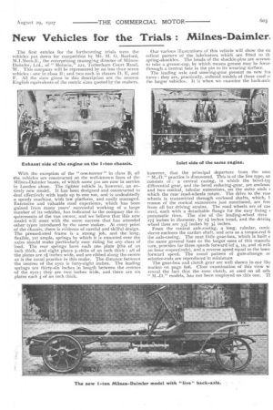
The first entries for the forthcoming trials were the vehicles put down for competition by Mr. H. G. Burford, M.I.Mech.E., the enterprising managing director of MilnesDaimler, Ltd., of" Motoria," 221, Tottenham Court Road, W. This company will be represented by no less than seven vehicles : one in class B; and two each in classes D, E, and F. All the sizes given in this description are the nearest English equivalents of the metric sizes quoted by the makers.
With the exception of the " one-tonner " in class B, all the vehicles are constructed on the well-known lines of the Milnes-Daimler buses, of which some 310 are now in service in London alone. The lighter vehicle is, however, an entirely new model. It has been designed and constructed to deal effectively with loads up to one ton, and is undoubtedly a speedy machine, with low platform, and easily managed. Extensive and valuable road experience, which has been gained from many years' successful working of a large number of its vehicles, has indicated to the company the requirements of the van owner, and we believe that this new model will meet with the same success that has attended other types introduced by the same maker. At every point of the chassis, there is evidence of careful and skilful design. The pressed-steel frame is a strong job, and the long, flexible, yet ample, springs by which it is mounted over the axles should make particularly easy riding for any class of load. The rear springs have each one plate iths of an inch thick, and eight plates 5-16ths of an inch thick : all of the plates are 21 inches wide, and are ribbed along the centre as is the usual practice in this make. The distance between
• the centres of the eyes is forty-eight inches. The leading spengs are thirty-six inches in length between the centres of he eyes ; they are two inches wide, and there are six plates each 4 of an inch thick. Our various illustrations of this vehicle will show the ex cellent pattern of the lubricators which are fitted to th spring-shackles. The heads of the shackle-pins are screwe, to take a grease-cap, by which means grease may be force, through a central hole in the pin to its wearing surface.
The leading axle and steering-gear present no new fea tures : they are, practically, reduced models of those used ol the larger vehicles. It is when we examine the back-axle
however, that the principal departure from the usu: " M.-1)." practice is discovered. This is of the live type, an consists of : a central casing, in which the bevel-tyr differential gear, and the bevel reducing-gear, are enclosec and two conical, tubular extensions, on the outer ends < which the rear road-wheels rotate. The drive to the roa■ wheels is transmitted through enclosed shafts, which, 1 reason of the conical extensions just mentioned, are fret from all but driving strains. The road wheels are of cas steel, each with a detachable flange for the easy fixing pneumatic tires. The size of the leading-wheel tires 274 inches in diameter, by 21 inches tread, and the drivint wheel tires are 331 inches by 3i inches. From the central axle-casing, a long, tubular, conic sleeve encloses the cardan shaft, and acts as a torque-rod fi the axle-casing. The neat little gear-box, which is built c the same general lines as the larger ones of this manufa lure, provides for three speeds forward (of 4, to, and 16 mild an hour respectively), and a reverse speed equal to the lowe forward speed. The usual pattern of gate-change ar selector-rods are reproduced in miniature
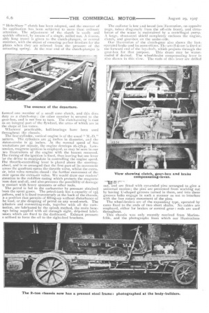
The gear-box and clutch gear are well shown in our illu tration on page 6o6. Close examination of this view w reveal the fact that the cone clutch, as used on all cal "M.-D." models, has not been employed on this one. TI " Hele-Shaw " clutch has been adopted, and the manner of its application has bcen subjected to more than ordinary attention. The adjustment of the clutch is easily and quickly effected, by means of a single, milled nut. A reasonably long travel is given to the clutch-plunger, or central member, with the object of ensuring perfect freedom for the plates when they are relieved from the pressure of the actuating spring. At the rear end of the clutch-plunger is
formed one member of a small cone clutch, and this does duty as a clutch-stop : the other member is secured to the gear-box, and is not free to turn. The clutch-casingis cast as an integral part of the flywheel, the arms of which are in the shape of fan vanes.
Wherever practicable, ball-bearings have been used throughout the chassis.
The four-cylinder, vertical engine is of the usual 3attern. The cylinders are 3 inches in diameter, and the 3iston-stroke is 5 inches. At the normal speed of 800 -evolutions per minute, the engine develops 16-17h.p. Low:ension, magneto ignition is employed, as may be seen in our :wo illustrations of the engine with the bonnet removed. The timing of the Ignition is fixed, thus leaving but one lever 70tthe driver to manipulate in controlling the engine speed. The throttle-controlling lever is placed above the steeringwheel, and is so arranged that the first part of its movement 'cross the quadrant opens the throttle valve, whilst the extra_ lir, inlet valve remains closed : the further movement of the ,ever opens the extra-air valve. We would draw our readers' mention to the red-fibre casing which protects the magneto 'ram dust and oil, and also prevents the possibility of damage Ar contact with heavy spanners or other tools.
The petrol is fed to the carburetter by pressure obtained ro/1.1 the spent gases. The petrol-tank has a capacity of 151 ;allons, and it is fixed transversely at the back of the chassis, n a position that permits of filling-up without disturbance of :he load,or..the dropping of petrol on any wood-work. The :ylinderS and -connecting-rods, together with all the camnotion, are lubricated, by the splash method, the main bearngs being supplied with oil through sight, drip-feed lubri!ators which are fixed to the dashboard. Exhaust pressure s utilised to force the oil to the sight-feed brackets.
The radiator is low c.nd broad (see illustration, on opposite page, takea diagonally from the off-side front), and circulation of the water is maintained by a centrifugal pump. A large, sheet-steel shield completely encloses the engine, clutch, and gear-box on the under-side.
Our illus.tration of the clutch-gear also shows the footoperated brake and its connections. 'Th.: small drum is fixed a!: the forward end of the lay-shaft, which projects through the gear-box for that purpose. This drum may be watercooled if desired. The wheel-brake compensating lever is also shown in this view. The ends of this lever are drilled
out, and are fitted with eye-ended pins arranged to give a universal motion ; the pins are prevented from working out by having U-shaped grooves turned in them, and into these grooves bolts engage in such a manner as not to interfere with the free rotary movement of the pins.
The wheel-brakes are of the expanding type, operated by cams fixed to the ends of two short shafts. No cables are employed, either, for brakes or control gear : rods are used throughout.
This chassis was only recently received from Marienfekle, and the photographs from which our illustrations.
have been reproduced were taken si'lortiv after its arrival in England. It will be fitted with a box-van body, the platform area of which will be 6 feet lon,, by 4 feet wide, and the height from the ground to the platform %yid be 2 feet, 6 inches. When completed, the vehicle will measure 13 feet, 2 inches in length, by 5 feet, 6 inches wide, and 8 feet high. The wheel-base is 8 feet, 6:1-, inches, and the gauge of the leading wheels is 4 feet 8 inches, that of the drivers being one inch less.
Other "M.-D." Entries.
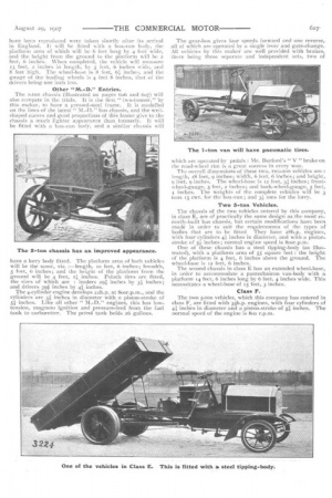
The 2-ton chassis (illustrated on pages 6o6 and 6o7) will also compete in the trials. It is the first " two-tonner," by this maker, to have a pressed-steel frame. It is modelled on the lines of the latest " M.-D." bus chassis, and the wellshaped curves and good proportions of this frame give to the chassis a much lighter appearance than formerly. It will be fitted with a box-van body, and a similar chassis will
have a lorry body fitted. The platform area of both vehicles will be the same, Viz. :—length, to feet, 6 inches; breadth, 5 feet, 6 inches; and the height of the platform from the ground will be 4 feet, pi inches. Polack tires are fitted, the sizes of which are : leaders 294 inches by 3 inches; and drivers 391 inches by 4 inthes.
The 4-cylinder engine develops 22h.p. at Soor.p.m., and the cylinders are 3; inches in diameter with a piston-stroke of 5; inches. Like all other " M.-D." engines, this has lowtension, magneto ignition and pressure-feed from the fuel tank to carburetter. The petrol tank holds 26 gallons. The gear-box gives four speeds forward and one reverse,. all of which are operated by a single lever and gate-change. All vehicles by this maker are well provided with brakes, there being three separate and independent sets, two of which are operated by pedals : Mr. Burford's " V " brake on the road-wheel rim is a great success in every way.
The overall dimensions of these two, two-ton vehicles are : length, 18 feet, 9 inches; width, 6 feet, 6 inches; and height, 9 feet, 9 inches. The wheel-base is 12 feet, 3; inches; frontwheel-gauge, 5 feet, 2 inches; and back-wheel-gauge, 5 feet, 4. inches. The weights of the complete vehicles will be 3 tons Is cwt. for the box-van ; and 3; tons for the lorry.
Two 3-ton Vehicles.
The chassis of the two vehicles entered by this company, in class E, are of practically the same design as the most recently-built bus chassis, but certain modifications have been made in order to suit the requirements of the types of bodies that are to be fitted. They have 28h.p.. engines, with four cylinders 41 inches in diameter, and with a pistonstroke of 5; inches ; normal engine speed is 800r.p.m.
One of these chassis has a steel tipping-body (as illustrated), with a platform area of 55' square feet : the height of the platform is 4 feet, 6 inches above the ground. The wheel-base is 12 feet, 6 inches.
The second chassis in class E has an extended wheel-base, in order to accommodate a pantechnicon van-body with a platform 14 feet, 6 inches long by 6 feet, 4 inches wide. This necessitates a wheel-base of 15 feet, 3 inches..
Class F.
The two 5-ton vehicles, which this company has entered in class F, are fitted with 3514.p. engines, with four cylinders of inches in diameter and a piston-stroke of 5; inches. The normal speed of the engine is Soo r.p.m.
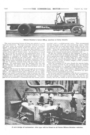
The most interesting feature of these two vehicles is a new -type of carburetter. We hope to be able to illustrate this, in -an early issue, by sectional drawings, and we reproduce LE:claw a photograph which shows its external appearance. The carburetter consists of : the usual float chamber ; a jet ,chamber, the upper part of which is of conical formation ; and. a piston type of throttle valve. As the piston is caused to rise or fall by the action of the hand-control lever, Or by the governor, the opening through which gas passes to the cylinders is enlarged or reduced, and additional air is -admitted or checked by the same piston. The general apTearanee of the carburetter is, perhaps, somewhat clumsy, .but, if the results attending its use are as satisfactory as we „are led to believe, external form will not weigh with engineers. We understand, from Mr. Burford, that this type -of carburetter has given such great satisfaction that all future vehicles, irrespective of size, will be fitted with it by his company.
Hot or cold air may be drawn in through the jet-chamber, -and the arrangement for the passage of hot air is rather ;novel. The exhaust-branch pipe is jacketed, and the upper -part of the jacket is perforated in order to permit the entry at air, whilst a socket at the lower end of the jacket fits into a. tunnel cast in the upper-part of the crank-case. The lower port of the jet-chamber is connected with this tunnel, and is
provided with a multiple-ported valve. This arrangement entirely dispenses with any inter-connecting pipes, which are always liable to work loose and to rattle, and the temperature of the air is also kept under control much more easily. When the multiple-ported valve is fully opened, the air is " shorted "; that is to say, it is not drawn through the jacket of the exhaust branch and is, therefore, cold.
Of the two vehicles entered by this company in class F, one will be fitted with an ordinary lorry body, and the other with a special lorry body suitable for brewers. The platform of each will be i3 feet, 4 inches long ; by 6 feet, 6 inches wide; and their overall dimensions will be : length, 22 feet, 6 inches ; width, 6 feet, 8 inches ; height, 9 feet, 9 inches ; with a 14-foot wheel-base.
With the exception of the new chassis for one-ton loads, all the vehicles entered by the company have its standard type of transmission, i.e., through a large-diameter, leatherfaced, cone clutch, to a 4-speed and reverse gear-box of the sliding-gear type, with a bevel-driven, differential-countershaft mounted on perch bars, and a final-drive by spurpinions and internal-toothed gear-rings.
By his early and liberal response to the R.A.C.'s announce_ ment of its intention to conduct the trials, Mr. Burford " set the ball a-rolling " towards a record entry, not only for this country, but for the world, so far as commercial motors go.