


THE NEW TWO-TON MAUDSLAY.
Page 10
Page 11
Page 12
If you've noticed an error in this article please click here to report it so we can fix it.
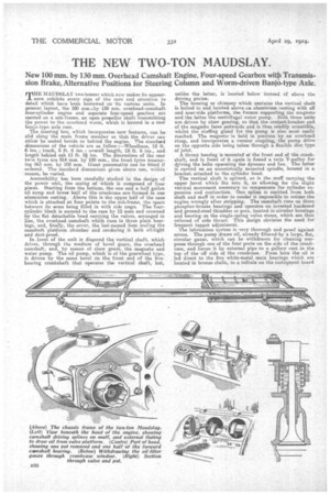
New 100 mm. by 130 mm. Overhead Camshaft Engine, Four-speed Gearbox witb Transmission Brake, Alternative Positions for Steering Column and Worm-driven Banjo-type Axle.
HE MACTDSLAY two-tenner which now makes its appearI_ sure exhibits every sign of the care and attention to detail which have been bestowed on its various units. In general layout, the 100 mat...by 130 mm. overhead-camshaft four-cylinder engine and separate four-speed gearbox are carried on a sub-frame, an open propeller shaft transmitting the power to the overhead worm, which is housed in a new banjo-type axle case.
The steering box, which incorporates new features, can be slid along the main frame member so that the driver can either be seated beside or behind the engine. The standard dimensions of the vehicle are as follow ;—Wheelbase, 12 ft. 6 ins.; track, 5 ft. 6 ins. ; overall length, 18 ft. 6 ins., and length behind cab 13 ft. 81 ins. The dimensions of the rear twin tyres are 91.4 mm. by 100 mm., the front tyres measuring 863 mm. by 100 mm. Giant pneumatics can he fitted if ordered. The standard dimensions given above can, within
• reason, be varied.
Accessibility has been carefully studied in the design of the power unit, the casing of -which is composed of four pieces. Starting from the bottom, the one and a half gallon
oil sump an i d lower half of the crankcase are formed n one aluminium casting. Above this is the upper half of the case which is attached at, four points to the sub-frame, the space between its arms being filled in with side trajs. The fourcylinder block is secured to the case by 12 nuts and crowned by the flat detachable head carrying the valves, arranged in line, the overhead camshaft which runs in three plain bearings, and, finally, the cover, the last-named item sealing the camshaft platform chamber and rendering it both oil-tight and dust-proof.
In, front of the unit is disposed the vertical shaft, which drives, through the medium of bevel gears, the overhead camshaft, and' by means of skew gears, the magneto and -water pump. The oil pump, which is of the gearwheel type, is driven by the same bevel On the front end of the fivebearing crankshaft that operates the vertical shaft, but.,
unlike the latter, is located below instead of above the driving pinion.
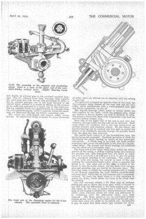
The housing or chimney which contains the vertical shaft is bolted to and located above an aluminium casting with off and near-side platforms, the former supporting the magneto and the Latter the centrifugal water pump. Both the..se units are driven by skew gearing, so that, the contact-breaker end of the magneto faces eutwards and is thus readily accessible, whilst the stuffing gland for the pump is also most easily reached. The magneto is held in position by an overhead strap, and incorporates a vernier coupling, the pump drive on the opposite side being taken through a flexible disc type of joint. A thrust bearing is mounted at the front end of the crankshaft, and in front of it again is found a twin V-pulley for driving the belts operating the dynamo and fan. The latter is carried on an eccentrically mounted spindle, housed in a bracket. attached to the cylinder head.
The vertical shaft is splined, as is the muff carrying the upper bevel which fits Into it, so allowing for the slight vertical movement necessary to compensate for cylinder expansion and contraction. One spline is omitted from both shaft and muff in order to render it impossible to retime the engine wrongly after stripping. The camshaft runs on three phosphor-bronze bearings and operates on inverted hardened and ground-steel thimbles or pots, located in circular housings and bearing on the single-spring valve stems, which are thus relieved of side thrust.. This design obviates the need for frequent tappet adjustment.
The lubrication system is very thorough and proof against errors. The pump draws oil, already filtered:by a large, flat, circular gauze, which can be withdrawn for cleaning purposes through one of the four ports on the side of the crankcase, and forces it by external pipe to a gallery cast in the tap of the off side of the crankcase. Front here the oil is led direct to the five white-metal main bearings. -which are located in bronze shells, to a telltale on the instrument board
arid, finally, by external pipe to the overhead h ft b • cams a bear ings. The oil, released from these bearings, then supplies the valve stem pots and, having thus performed its duty, is led by suitable passages cast in the head forward to the vertical drive, whither it, is drawn by fluting on the exterior of the muff and rearward to a return way to the crankcase. The top camshaft bevels are supplied direct, by a by-pass from. the valve platform piping, which is exposed, whilst the small• ends are lubricated through the hollow connecting rods. The valves are tulip-shaped and employ single return springs. No adjustment being necessary for many thousands of miles, users are advised not to interfere with the setting as sent out.
Thu ports are arranged on opposite sides of the head, the four exhausts being located on the near side and the twin inlets, which communicate with a water-jacketed inlet pipe and Zenith carburetter, on the off.
The big-end bearings (white metalin bronze shells) are held together by two bolts, whilst the gudgeon pins, which are located in bronze bushes, are held in position by bolts. The piston is fitted with three wide compression rings and one eccentric-pinned scraper ring. Each side of the upper half of the case is cast with four windows, through which the big-ends can be detached. Each cover closes two windows and in one case incorporates an oil-filler chimney and crankcase release. By this means, the big-end bearings can be reached and then split to enable the pistons to be withdrawn upwards through the cylinder barrel after the bead has been removed.
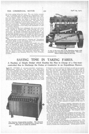
The leather-faced clutch is of the inverted-cone type, the spring being self-contained. Excellent provision is made for lubricating the spigot bearing by means of two grease-gun connections. A. clutch stop is provided, the fixed portion extending right across the sub-frame in the form of a doubleended banjo. The journal and thrust bearings are combined and the whole job 1S extremely neat. The front end of the clutch shaft. slides within the driven portion of the clutch, a sliding coupling being also found at the gearbox end. The four-speed box, the ratios of which are 1 to 1, 1 to 1.73, 1 to 2.88 and 1 to 5, is, like the power unit, four-point attached to the sub-frame. The whole job is stiff, 'solid and strong, the outside or back of'the case carrying the transmission-brake collar, which is spigoted and bolted to it. The outer end of the collar is bolted to the frame to take the brake torque, and the brake-shoe fulcrum pins and actuating cam are carried by the same piece. The revolving drum is ribbed for cooling purposes and is belted to the housing containing the front tubular propeller-shaft .universal joint, which tuns on ball bearings and is completely enclosed. To reach the brake shoes it is only necessary to unbolt the dram, which allows the shoes to be lifted clear for relining. The rear universal utilizes a De Dion type of enclosed sliding pot and so drives the worm gear, which is 'housed in one unit with the differential in the banjo-pattern axle case. The latter, by the way, is forged from a solid billet. The back of the forging is covered by a domed aluminium casting, which,when removed, allows the worm and differential to be withdrawn after the differential shafts havebeen removed. The latter operation can be performed without jacking up the road wheels, by simply removing the hub caps, which then allow the shafts to be pulled out,. Incidentally it may be noted that these shafts only transmit the drive,
the banjo casing taking the load. The rear brakes measure 18 ins, in diameter and are operated by compensating cable. Extra long half-elliptic springs are fitted•above both axles, ithe -road wheels, which are bolted to the hubs and run on ball and roller bearings, are made of east-steel, the spring brackets and dumb-irons being mild steel, The dished front axle is a steel stamping, its swivel pins being canted. A collision bar is provided, the radiator being mounted on the front tubular cross-member. Vertical gilled tubes are used, the top and bottom aluminium covers being made detachable in order to facilitate cleaning.
The steering box has been redesigned, the worm and sector shafts running on Timken taper roller bearings and a full worm wheel being provided, so that the maximum life is obtainable. As already Mentioned, the steering column can be mounted forward or in a more backward position. The ignition and throttle controls are located on a fixed quadrant above the centre Of the steering wheel, while the brake and gear controls arc. placed conveniently to the driver's right hand.
There has been. a great deal of "cleaning up" throughout the whole design of the two-tonner and every consideration has been paid to economy in manufacture.
The frame consists of two straight and parallel side members, the channels of which face outwards. These members klie cross-tied by four tubular members, the front pair carrying the sub-frame and the rear pair being attached adjacent to the rear-spring brackets, the spring centres being 4ft. 6 ins. apart. The sub-frame is sunk in relation to the main frame and the chassis is fitted with grease-gun lubrication. The makers' address is the Maudslay Motor Co., Ltd., Parkside, Coventry.