


THE MARTIN TRACTOR. a
Page 38
If you've noticed an error in this article please click here to report it so we can fix it.
A Résumé of Recently Published Patents.
It is quite in keeping with' the general fitness of things that our interest, this week, should be mainly with an agrimotor, since 'to-day will 'see the opening of the Lincoln Tractor Trials, the most important event, nowadays, of the agricultural year. W. E. Martin, who describes his tractor in specification No. 149,486, is well
known to all tractor users. His Selfcontained motor plough was presented to the public in the earlier days of the tractor, and had, besides several features of novelty, as well as being ingenious in design and construction, the advantage of being designed and made by an exparienced manufacturer of agricultural machinery. It .remains to this day, we believe, the only self-contained machine which runs on a self-laying track. Last year, at Lincoln., the same maker brought out a new machine, a tractor pure and simple, which •performed most satisfac torily at the trials. Evidently, in the period which has elapsed since that , event, he has devoted considerable atten-lion to its 'design, and some of the improvements which he has• made are apparent from the perusal of the specification to which we refer. 11 is, therefore, well worth our special attention this week.
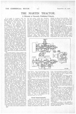
The tractor itself, as many readers will recollect, is of the four-wheeled type, and designed as a general purpose machine. It is heavy and strong enough forroad traction, and is fitted not only with a belt pulley, but also a winding drum. The present specification is mainly concerned with the transmission, and in particular with the gearbox. It is the latter which we illustrate, and to which the following description refers. It should be noted in the first place that this component is not disposed in the usual fashion, with its shafts, etc., in line with the axis of the chassis, butlies across the frame. The first reduction, from the engine, is by bevel gears, there being a pinion of that, type on the clutch shaft, engaging with a crown wheel which revolves freely on ball bearings which are carried by the main cross-shaft of the gearbox. The back 'Of the crown wheel is constructed so as to be, in effect, an internally toothed spur wheel. The gearbox layshaft has three wheels keyed, or mined, to it. They are incapable of any lateral movement, The largest of than, situated midway between the other two, is constantly in engagement with a gearwheel which is integral with the crown wheel, and it will be realized, therefore, that the layshaft revolves whenever the clutch shaft is in motion. There are two sliding gears on the main cross-shaft of the gearbox, that shaft oh which the crown wheel of the main bevel drive revolves. One of them
• may engage either with one of the wheels on the layshaft, or with the internal gear Of the crown wheel, into which it slides, thus acting as a dog clutch. The other may engage either with the remaining ,wheel on the layshaft, or with a reverse pinion of the familiar type. The arrange• ment affords,three speeds, of which the top•gear, obtained by the engagement of the pinion with the crown wheel, is direct. The construction is interesting, as it eliminates the usual feature of such a gearbox, that of the divided main shaft.
At one end of the main cross-shaft is B32
the belt pulley which has, therefore, not only the advantage that it can be driven at either of the three speeds or reverse of the box, but also, and this is particularly important, is controlled by the engine clutch, and may be liberated or engaged instantaneously. At the other end of the same shaft is a pinion mounted on spines, so that it can be slid along the shaft. In one of its two main positions it engages with a large spur wheel on the differential gear. In the other it is free. The differential gear is mounted on a countershaft carried on the chassis frame, and the differential shafts carry at their ends pinions which, normally, engage with internal gears bolted to the spokes or rims of the rear
road wheels. One of these pinions, however, can also slide upon its shaft, and may be disengaged from the gear on the road wheel, and enmeshed with a spur wheel which is bolted to a winding drum running freely on the rear axle of the, tractor.
The operation of the gear will be fairly obvious. When the sliding pinion On the gearbox cross-shaft is out of engagement with the gear on the differential; the belt pulley is available for use. When it is engaged with the differential gear, hut the pinion on the differential shaft is out of engagement with the ring on the road wheel but in mesh with that on the winding drum, it is only necessary to chock one of the road wheels, preferably that on the opposite side to the drum, in order that full use.may be made of the
latter. Much of the specification • is taken up with a description of the operating gear for the box.
Detail Improvements.'
Most tractors are DOW fitted with some nieans of washing the air which is induced into the engine, for the purpose of removing the du-.t which it naturally contains when the machine is at work in the fields on a dry day. One such cleaner is described in specification No. 129,967, by Henry Ford ind Son. As is i customary n most of these fittings, the air is drawn through water on its way to the carburetter, and the principal feature of this design appears to be that the air, after it leaves the water, is again deflected on to the surface of the water . before leaving the apparatus. The principal point of intaiest in the trailer attachment described in No. 1149,534, is that it allows of the drawbar being made rigid or flexible, a facility which is advantageous when rnanceuvring. The patentee is F. Crocker. No. 149.464 by V. G. Macario, concerns a hood for a motor coach. It is made in two parts, the division being a longitudinal one, along the top of the hood. It is attached to a series of "lazytongs," by means of which the two halves are each folded up into a casing along the side of the vehicle.
The supplementary 'springing system' which is described in No. 149,548, by G. G. F. Boswell. is shown applied to a Ford' car, for which it is mainly suitable. The shackle, if replaced by a pair of brackets, between which is a coiled spring. The novelty, appears to lie in the disposition of the brackets, which are so arranged that one of them fulcrums on the main spring at a point some distance 4 froze its end.
No. 149,496 shows a simple method of coupling the ends of two semi-elliptic • springs an as to form tle complete elliptic. The end of the main leaf of each spring is turned outwardly, and the two adjacent ends are enclosed, with wood packing, in a cylindrical component. The patentee is G. A. Phillips. In the carburetter, which is the subject of patent No. 126.642, the annular jet is placed in a venturi choke tube, which slides 'up and down as influenced by the engine suction. The patentee is F. R. Sunderrnan.
F. Recldaway shows, In No. 149,503, a method of constructing a flexible track for track-laying machines. It is made of rubber and canvas. .