


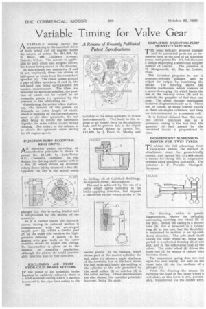
Variable Timing for Valve Gear
Page 40
If you've noticed an error in this article please click here to report it so we can fix it.
A Résumé of Recently Published Patent Specifications. AVARIABLE timing device for incorporating in the camshaft drive of both petrol and oil engines forms the subject of patent No, 511,853, by B. Read, 295, Chalmers Avenue, Detroit, U.S.A. The scheme is applicable to both chain and all-gear drives, the former being shown in the drawing.
In this scheme two camshafts (2 and 6) are employed; these are driven at half-speed by chain from the crankshaft sprocket (4). The chain passes around a pair of idler sprockets (3 and 5), the left-hand one being spring-loaded for tension maintenance. The idlers are mounted on movable spindles, the position of which can be varied by an hydraulic piston (1) operated by the pressure of the lubricating oil.
Considering the action when stationary, the descent of the piston (1) demands an extra length of chain, which is supplied by the outward movement of the idler sprockets, the net effect being to rotate the camshafts slightly; the same action occurs during running. The object of the scheme is to obtain the optimum valve setting for all engine speeds.
INJECTION-PUMP ECCENTRICRING DRIVE.
AN injection pump operating on unorthodox principles is shown in patent No. 511,921 by Auto-Union A.G., Chemnitz, Germany. In this design, the driving shaft carries with it a disc (5) which drives an eccentric rotary sleeve (4) by means of a key (6). Opposite the key is the actual pump
plunger (2); this is spring loaded and is reciprocated by the motion of the eccentric.
As it is carried round the eccentric sleeve, during its outward motion it communicates with an arc-shaped supply port (3), whilst a similar port (7) on the other side receives the highpressure delivery. A pinion (1) engaging with gear teeth on the outer member serves to adjust the timing. No information is given as to the method of quantity regulation, although the pinion (1) could conceivably function also in this direction.
EXCLUDING AIR FROM HYDRAULIC BRAKE SYSTEMS.
I F the pedal of an hydraulic brake
system be suddenly released, there is a brief moment during which a suction is created in the p:pe-lines owing to the
inability of the drum cylinders to return instantaneously. This leads to the ingress of air should there be the slightest leak, and to prevent this is the object of a scheme shown in patent No. 512,029, by J. Pratt, G. Manley and A. Girling, all of Guildhall Buildings, Navigation Street, Birmingham.
The end is achieved by the use of a valve which opens instantly in the brake-applying direction, but imposes a restriction on the return stroke of the master piston. In the drawing, which shows part of the master cylinder, the ball valve (1) allows a rapid discharge of the contents, but on the back stroke the ball scats and limits the refilling of the cylinder to the rate permitted by the small orifice (2) or notches (3) in the valve seating. Other modifications are also shown, the essential principle, however, being the same. SIMPLIFIED INJECTION-PUMP QUANTITY CONTROL.
THE usual helically grooved plunger and its associated parts are an expensive item in the cost of an injection pump, and patent No 510,748 discloses a design employing a somewhat simpler method of control. The patentee is H. Morgenroth, 40, Rue de Colisee, Paris.
This inventor proposes to use a constant-delivery plunger, and to adjust for output by restricting the intake. The drawing shows the throttle mechanism, which consists of a screw-down plug (1) which limits the rise of the one-way valve (3) and so controls the quantity of fuel that can pass. The usual plunger mechanism is shown diagrammatically at 2. There are, of course, as many control valves as there are engine cylinders, and they are interconnected by a common rod.
It is further claimed that this control device functions also as a governor, owing to the fact that the quantity of fuel passed by the restricted intake is proportional to time.
INDEPENDENT SUSPENSION SYSTEM FOR TWIN TYRES.
TO obtain the full advantage from twin-tyred wheels, the method of attachment must be geometrically correct, and patent No. 511,808 shows a means for doing this in suspension systems using swinging half-axles. The patentee is F. Porsche, Stuttgart, Germany, The drawing, which is purely diagrammatic, shows the swinging axle-casing carrying one wheel (2) of the pair. Inside the casing is a second tube (5), this is mounted in a rubber ring (6) at one end, but the flexibility is restrained to motion in an up-anddown direction. The axle shaft itself carries the outer wheel (4), being supported in a spherical housing (3) at one end, and in the differential case at the other. The outer wheel (4) drives the inner one (2) by means of rubber keys between them.
The suspension spring does not rest upon the axle casing, but acts on the inner tube (5) via the medium of a plunger (1).
From the drawing the means for carrying the load of the inner wheel is not clear, as this force is not, presumably, transmitted via the rubber keys.