


ANOTHER AUTOMATIC CHANGE-SPEED GEAR.
Page 36
If you've noticed an error in this article please click here to report it so we can fix it.
A Restund of Recently Published Patent Specifications.
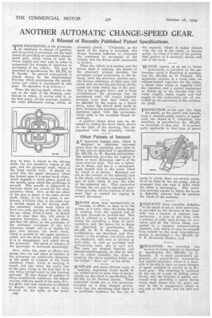
mHE PROPERTIES of the gyroscope, 1 its resistance to change of position, and its powers of.precession are the basic means of providing an automatic change. speed gear, which varies in ratio between engine and rear axle in order to compensate for changes of resistance to movement of the vehicle. The gear is described in specification No. 221,725, by i H. Gooder. Its general arrangement s clearly shown by. the diagrammatic drawing which accompanies the specification and which is reproduced on this page. Its operation is as follows:— When the driving shaft, which is the one on the right of the drawing, commences to rotate, it carries with it, in the first place, all the gearings, namely, the outer differential casing, which, as may be seen, is keyed to the driving Shaft, the two planetary wheels of the gear, and the gyroscope itself, which is the large central body. It should be noted that the upper planetary wheel has formed upon it a second bevel wheel, which engages a bevel pinion keyed to the spindle upon which the gyisiscope is secured. This spindle is supported in bearings which are carried by the other planetary wheel. Now, as the sun wheel of the gear is keyed to the main driven shaft; which, in the first place, is stationary, it follows that, as the outer case is carried round by the driving shaft, the planetary wheels must rotate on their own axes, gearing, as they do, with the sun wheel, which is held. It should also , be clear that they will rotate in opposite directions, one to the other, and that the effect, on the gyroscope, of the combined movement of the two planetary wheels will be to double the gear ratio between the bevel wheel, which is carried by the upper planetary wheel, and the bevel pinion with which it is in engagement, and which drives the gyroscope. The speed of rotation of the gyroscope is increased accordingly.
Now, while this state of affairs continues, the axis and plane of rotation of the gyroscope are continually changing, at the speed of rotation of the lower planetary wheel, which is carrying it round, and also about the centre line of the gear, owing to the fact that it is also being carried round by the rotating gearcase. To this change of position it offers considerable resistance, the degree varying with the speed of the main driving shaft, and that resistance is reflected in torque, which appears as • a force directed on the teeth of the lower C52 planetary pinion. Ultimately, as the speed of the engine is increased, this torque becomes sufficient to overcome the resistance to movement of the vehicle, and the driven shaft commences to revolve.
When the vehicle is in motion, and the driven shaft is rotating, the speeds of the planetary pinions decrease, the gyroscopic torque conforming to the demand, until the planetary pinions actually become stationary on their axes, but rotate with the driving and driven shafts, round the main centre line of the gear. This is the top-gear drive, and in these circumstances the gyroscope can be maintained until the torque required becomes more than that which can be afforded by the engine as a direct drive, when the driven shaft tends to slow, bringing the planetary pinions into operation again with the, gyroscope, which adds to the available torque accordingly.
A positive direct drive may be obtained by sliding the bevel wheel, shown on the right of the drawing, into engagement with the planetary wheels.
Other Patents of Interest.
AN ingenious tipping gear, which is
designed to eliminate universal joints from the operating gear—that is, all but one—is described in specification No. 221,746, by W. Barnett and another. The mechanism provides for tipping in three or more directions, and is of the screw-and-nut type. The nut is spherical in shape, and fits in a correspondingly shaped hole in the worm wheel by which it is driven. Keyways are cut in the interior of the spherical hole in the wheel, and these are engaged by a pair of balls which fit into the sides of the spherical nut. This connection • between the nut and its operating gearwheel provides all the freedom of movement that is needed for tipping in several directions.
BRAKE shoes tend automatically to increase in effect, to draw on to the drums, as it were, when the brake drum is rotating from the applied end of the shoe towards its pivoted end. This fact is utilized in a simple manner as mearis for providing a form of servo operation, and the means for so doing are described in specification No. 221,635, by W. S. Renwick. Several modifications are described and illustrated; in the simplest, two brake shoes are employed, and each is pivoted at both ends, as well as provided with self-centring cams, also at each end. The cams are coupled together and operate simultaneously, so that no matter in which direction the drum is rotating, the above condition holds, and the brakes "draw on" to the drum.
SIMPLER and more efficient ways of applying segmental brake bands to the rubber-tyred or plain rims of tractor wheels are described in specification No. 221,653, by Sir Herbert Austin. These segmental treads are, in this invention, mounted on a deep channel section, which has the advantage that there is no particular tendency for the rim of the segment, where it makes contact with the rim Of the wheel, to become soiled, for when it is laid on the ground, that portion of it naturally stands well out of the mud.
WATER vapour, as an aid to better
carburation, is provided in the carburetter which is described in specification No. 221,656, by W. Pickard. His apparatus consists of a water tank, an exhaust-heated vaporizer for the water, a steam chest which is supplied from the vaporizer, and a control mechanism' so linked up to the throttle that the water supply, steam supply and fuel .supply to the carburetter, are all controlled by the movement of the accelerator pedal.
PROTECTION of the user who buys his petrol, or his petrol and benzole, from a wayside pump station, is apparently the object of C. Chambers, who describes, in specification No. 221,608, an invention to that end. It is principally applicable to that type of petrol pump in which there are several tanks, all to be filled by the one pump and so arranged that one tank is filled while the other is discharging. This invention provides signals by which the buyer is definitely assured that he receives the whole of the contents.
IMMUNITY from complete deflation • as the result of one or more punctures, is provided by the division of the inner tube into a number of separate compartments. A tube of this kind, with a number of cells, each baying its own valve, and all the valves being connected to a common communicating chamber, into which air may be pumped from outside by the usual tyre-inflating means, is described in No. 221,537, by T. B. McLeroth (Tubes), Ltd.
1VIECHANISM for reversing the motion of motor vehicles is described in specification No. 208,124, by L. Renault. It is more particularly applicable to petrol-driven locomotives and similar machines, where it is desirable to be able to have as many changes of speed available in reverse as in forward gear. The reversing is achieved by the use of a pair of sliding crown bevels, and the inventor is mainly concerned with providing a safety device which shall ensure that the gears can only be left in engagement, either to one side or the other, and not half and half.