


For DRIVERS, MECHANICS & FOREMEN.
Page 23
If you've noticed an error in this article please click here to report it so we can fix it.
A PRIZE OF TEN SHILLINGS is awarded each week to the render of the best letter which we publish on this page all others are paid for at the rate of a penny a lane, with an allowance for photographs. All notes are edited before being published. Mention your employer's name, in confidence, ao evidence of good faith. Address, D., M. and F., "The Commercial Motor," 7-1,5, Rosebery Avenue, London, PLC. I.
Lamps Alight.
On Saturday, November 1st, light your lamps. at 5.3 in London, 5.8 in Edinburgh, 5.0 in Newcastle 5.10 in Liverpool: 6.9 in Birmingham, 5.13 in Bristol', and 5.63 in Dublin.
Improving a Steering Gear.
The sender of the following communication has been awarded the Ws. prize this week..
[2026] " F .N ." (Guildford) writes :—" In your issue of August 26th a contributor to the D.M. and F.' page draws attention to a well-known failing of the majority of steering gears, in that they are seldom designed so that they can be adjusted for wear, and
that even where adjustment is provided it is frequently very inaccessible. I may say that I entirely agree withyour correspondent., and I too have had a good deal of experience in the matter. In one chassis at least, however, that I know, adequate and accessible means of adjustment for wear were provided, but other troubles arose because of the faulty design of the steering gear, and I thought perhaps some of your readers might be interested in knowing what they were, how I got over them, and, finally, how I improved the gear and eliminated the fault which was the cause of so much trouble. The experiences to which I am about to refer took place in France.
" The design of the gear is roughly shown 'by the . accompanying sketch (which we have had redrawn— En.). The worm was held between two cup-and-cone races of the bicycle type. The upper one was supported by a screwed collar which was fixed in place on assembly by the makers. To prevent it from slipping it was secured, after adjestment, by a small setscrew. The lower one was -adjustable at any time, the nut being locked by means of a. small plate fitting into one of a score of nettles cut in the circumference of the adjusting nut. The cones of • the ball races were cut. from the worm shaft, with which they were one piece, and therein lay the chief ca-use of
trouble. Another thing which operated against the satisfactory working of the gear was the fact that the balls were not carried in a cage. "The first thing to happen usually was that the balls, running on the edge of the worm, were chipped. Subsequently, and very shortly afterwards, the races broke, the balls ran away, got mixed up with the steering gear, and looked it. "After one or two occurrences of this nature we decided to try what we could do in the way of
improvir. on the maker'S handiwork. The distance from face to face inside the box, measured along the centre line of the worm, was n ins. The two haives of the box were set up in the lathe separately and faced out until the distance was increased to 41 ins. The worm was then softened, the cones turned off at each end, so that a practically square corner was' made. The ends were turned to 44 mm. for acombined thrust and radial bearings which we had decided to fit. Similar recesses were then formed on the inner ends of the adjusting collars, and a pair of proper combined bearings was then fitted. Finally, the worm was re-hardened and the whole gear re-assembled. The job was most satisfactory, and was afterwards standardized for all models of that make of lorry."
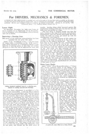
Motor Lorry Davits.
[2027]'" HAI." (West Bromwich) writes :—" I have seen several examples lately of the fitting of jib cranes or similar accessories to motor lorries, and these are undoubtedly very useful in quite a number of the classes of work which a motor lorry is called upon to perform. I was reminded of a letter which I submitted to the 'DM. and F.' page of The Commercial Motor many yearr ago, and I suggest that the present is an opportune moment for republishing the sketch and description. " Near the rear end of the lorry, and to one side, fit a, bracket, as sketch (C). It should be, as near as possible just over the rear axle. Take a piece of tube 3 ins, diameter outside and -1 in. thick ; taper it down.at one end, and weld an eye piece to it, bending the solid end over as shown on the sketch so that the axis of the hole is vertical. Take an eye bolt and slip it through the hole in the end of the davit so that it acts as a swive . Into the eye bolt can be slid the hook of a set of chain blocks, differential winch, or similar contrivance. The fitting can be used almost in the same way as a, jib crane' picking loads up from the side or rear of the. lorry, swinging them round and forward for deposit on the lorry itself, or vice versa for tinjoading. Its advantage is economy."