


FORD VAN POINTERS.
Page 21
Page 22
If you've noticed an error in this article please click here to report it so we can fix it.
By R. T. Nicholson (Author of "The Book of the Ford").
TRE FORD ton truck is now on sale in America : indeed, it has been offe,red for sale "over there" for quite a time past, and numbers of such trucks were used in the war. At present, however, the Ford Co. in this country will not accept orders for the truck, having, already more than enough orders on hand for their other classes of vehicles.
147.—The Ford Ton Truck.
The Ford ton truck does not differ in essentials from the Ford van, except that it gives larger stowage room, and is built to take far greater weights— weights up to a ton.
Its wheelbase is lengthened ; back tyres are solid ; its drive is a worm drive. This last feature is the main difference between the ton truck and the other types of Fords.
The buyer gets a chassis only ; he fits his own bodywork.
On these Ford trucks there is a new electric-light switch. It is combined with the horn button and is
placed on one side of the steering column. To sound the horn the button is pushed in in the usual way, except that it is pressed from the side. To switch on the lights the same button is turned. Its novelty lies in the fact that it is a two-way switch. It has three possible positions—full on, half on. and off. It is placed in the full-on position for ordinary running in high gear. It is placed in the half-on position for running in slow speed. At such speed, though the truck itself is running slowly,, the engine is turning over very quickly, and so sends a lot of
current to the lamps. With the ordinary outfit, having a one-way switch, this means that the lamps are in danger of being burnt out ; and, in paint of fact, lamp failure on Fords is largely due to the strain put on them when runnuig. at slow speed. With the new arrangement, and with the switch set in the half-on position, the current that can reach the lamps is kept about as it should be, so that there is only the ordinary (light) strain on them.
I48.—The Ford Horn.
For traffic driving I am not in love with the standard Ford horn. When the van is going a good "hat," the horn gives all the noise that is needed to buck up the driver ahead ; but. when it, is running slowly—as is often the case in traffic--the note of the horn is a poor thing. For traffic driving a horn of the Klaxon type is the only thing. Its note truly is a thing_ of horror ; but that's just why it wakes up the man ahead. Round corners the Ford horn is very thin stuff—a mere bee buzz.
You can make a useful clamp out of a strip of tinned iron and a bolt and nut. Take a strip of iron a bit longer than the pipe,. cylinder or other round thing on which the clamp is to be used. By " a bit longer" I mean from 1 in. to 2 ins., accord. ing to the nature of the job in hand. Then, near each end of the strip, drill a hole to take your bolt. Pass the strip round the thing that you want to clamp. Slip the bolt through and turn the nut, tightening it until the strip is firmly clamped on.
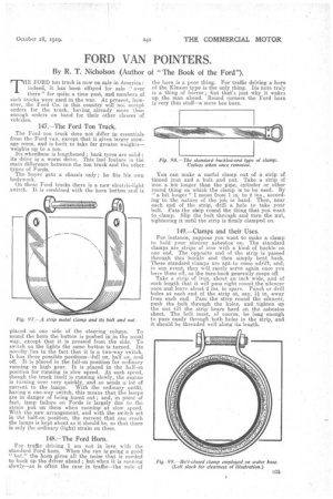
149.—Clamps and their Uses.
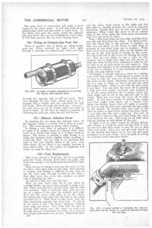
For instance, suppose you want to make a clamp to hold your silencer asbestos on. The standard clamps are strips of iron with a kind of buckle on one end. The opposite end of the strip is passed through this buckle and then simply bent back. These standard clamps are apt,to come adrift, and, in any event, they will rarely serve again once you have them off, as the turn-back generally snaps off. Take a. strip of iron, about an inch wide, and of such length that it will pass right round,the silencer once and leave about 2 ins, to spare. Punch or drill holes at each end of the strip at, say, 1i in. away from each end. Pass the strip round the silencer, push the bolt through the holes, and tighten up the nut till the strip bears hard on the asbestos sheet. The bolt must, of course, be long enough to pass easily through both holes in the strip, and it should be threaded well along its length. The same kind of contraption will make a good clamp for the water joints. It will also hold on an exhaust-pipe pack nut that tends to work loose. In the latter case pass the clamp round the exhaust pipe just below the nut and touching its lower edge. It will then prevent the nut from turning back.
150.—Fixing an Exhaust-pipe Pack Nut.
There is another way of fixing. an exhaust-pipe pack nut.. When screwed up tight, drill right through it, through the exhaust-pipe walls, and then through the opposite side of tiles nut itself. Then pass through all four holes (which must be in a straight line) a sturdy split pin, and bend the legs well back. This will make the pack nut " stay put" for ever more—or, at all events, until you want to slack it back. It will then be simply a question of removing the split pin, when the nut will be free.
151.—Silencer Asbestos Cover.
In washing the van keep the cleaning water off the silencer, which is covered with a sheet of asbestos. This covering goes to pieces when soaked. In fitting a new sheet of asbestos it is difficult to make it lie snugly round the silencer shell, inasmuch as it cracks and warps as it is -bent round to shape. The secret of getting a, snug fitting is to damp the asbestos sheet slightly before bending it round -the shell. Do not soak it—or anything like soak it—but just slightly damp it all over ; and, when damp, do not treat. it too roughly, because it then tears easily. It will regain its toughness and retain its -snug fit when dry.
152.—Tyre Replacement.
This is not strictly a Ford tip ; but it is specially. good for Fords, because Ford tyres are light, and what I am going to say holds good especially for light tyres. Most drivers in fitting a tyre put the cover on the rim first; then they poke in the tube, often getting it twisted, and finding it difficult, in any case, .to get the valve stem through its hole in the wheel ; then they lever the cover into position at great risk of pinching the tube. Do not do it that way, but this way : Blow up your inner tube till -it just takes its rounded shape—not more than enough to make it do that. Then, with the cover off the wheel, slip the tube into position. That is perfectly easy, and you can see at a glance if the tube lies straight and snug. Now put the cover, with tube, on to the wheel, first fitting the valve stem into the hole in the wheel provided for it. Then lever on the cover, with the tube, beginning opposite the valve hole. It will go on for quite a way "'by hand," however, without your using the levers. You work with the idea of getting both beads over the wheel at once—not leaving one out to be forced over later ; it is quite-as easy to get both beads over as one. Beginning oppo e36
site the valve, work evenly to the right and the left—that is, equally towards the valve in opposite directions, seeing that you do not pull the valve sideways. Then, when the cover is all in except close to the valve, push -the valve stem downwards
i and lever the cover n there.
Note.—You lever from one rim only—not first from one side and then from the other. Use tbree levers. Get the wheel flat on the ground, if possible,so, that you can kneel on the levers to hold them in position as you work from one to another. When three levers are in position, take out the middle one for use at the next point of attack on the cover. Use the hook end of the levers for forcing the cover on. You are not likely to nip a tube bythis method ; but to make sure that you will not do so slide the hook of the lever sideways to and fro for an inch or so at each point as you insert it. You
an then feel whether it lies touching only the metal of the rim or whether it is also touching the rubber of the tube and risking a nip. •
Personally, I always remove a cover in a similar way—with tube inside. I find that it is easier to do so than to take the tube out of the cover; leaving the cover on the wheel. Moreover, once the cover is off it is easy to shake (or blow) out the dirt that Will collect inside. -(Blow it out with the tyre pump if you like.) You can start the cover off by passing a long tyre lever under one. bead, then pushing it on in the same direction till it •passes under the other bead, and so out at the opposite side of the wheel. Then you can lever the cover off at both beads. If you have trouble in getting the single tyre lever under both beads, use a second lever under the farther bead' that will make it. possible for you to slip the first lever through the gap made by the second. Be careful when you come to the valve to press it right down before you lever there, or you may tear the valve right out. You will, of course, have removed the nut that holds the valve stem down to the rim. This must be off both when you are putting on and taking off the tyre.
If there were no other reason for having detachable wheels, it would be worth having them if only for the fact that they make it easy for you to deal with your tyres. Once you can get your wheel On to the ground and kneel on it, you can get some purchase on to your work. It is as good as sitting on a horse's head when he's down.