


Patents Completed.
Page 22
If you've noticed an error in this article please click here to report it so we can fix it.
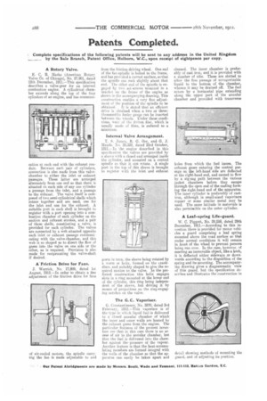
A Rotary Valve.
E. C. R. Marks (American Rotary Valve Co. of Chicago), No. 27,901, dated 12th December, 1911.—This specification describes a valve-gear for an internal combustion engine. A cylindrical chamber extends along the top of the four cylinders of an engine, and has communi cation at each end with the exhaust conduit. Between each pair of cylinders, connection is also made from this valvechamber to either the inlet or exhaust passages. These latter are arranged alternately from one end so that there is situated on each side of any one cylinder a passage from the inlet, and a passage to the exhaust. The valve itself is composed of two semi-cylindrical shells which rotate together and are used, one for the inlet and one for the exhaust. A suitable port in each shell is brought to register with a port opening into a combustion chamber of each cylinder on the suction and exhaust strokes, and a pair of these shells, constituting a valve, is provided for each cylinder. The valves are connected by a web situated opposite each inlet or exhaust passage communicating with the valve-chamber, and this web is so shaped as to direct the flow of gases into the valve on one side or the -other, as is required. Provision is also made for reciprocating the valve-shaft if desired.
A-Friction Drive for Fans.
.1. Warrick, No. 17,809, dated 1st August, 1912.—In order to obtain a line adjustment of the friction drive for fans of air-cooled motors, the spindle carrying the fan is made adjustable to and from the friction driving wheel. One end of the fan-spindle is bolted to the frame, and has provided a curved surface, so that the spindle can rock slightly about that end. The other end of the spindle is engaged by two set-screws mounted in a bracket on the frame, of the engine as shown in the accompanying drawing. This construction enables a very fine adjustment of the position of the spindle to be obtained. It is stated that an efficient drive is ebtained when a two or threethousandths feeler gauge can be inserted between the wheels. Under these conditions. wear nf the driven disc, which is usually made of fibre, is reduced to a minimum.
Internal Valve Arrangement.
T. James, R. G. Orr, and. G. J.
Maude. No. 23,332, dated 23rd October, 1911.—In the engine described in this ,specification the valves are provided by a sleeve with a closed end arranged inside the cylinder, and mounted on a central spindle so that it can rotate. A single port in the top of this sleeve is brought to register with the inlet and exhaust ports in turn, the sleeve being rotated by a worm or helix, formed on the crankdiscs, and suitably shaped to give the required motion to the valve. In the preferred construction this helix engages slots in a ring mounted at the lower end of the cylinder, this ring being independent of the sleeve, but driving it by means of projections on the ring-engaging notches on the valve.
The G. C. Vaporiser.
G. Constantinesco, No. 2870, dated 3rd February, 1912.—This vaporizer is of the type in which liquid fuel is delivered to a closed annular chamber of which the inner and outer walls are heated by the exhaust gases from the engine. The particular features of the present invention are that in this case there is no access of air to the annular chamber, but that the fuel is delivered into the chamber against thepressure of the vapour. Another feature is that the heat-accumulatiug members are formed integral with the wells of the chamber so that the apparatus can easily he taken apart and cleaned. The inner chamber is preferably of cast iron, and it is provided with a number of ribs. These are slotted to allow the free passage of unvaporizable liquid to the bottom of the chamber, whence it may be drained off. The fuel enters by a horizontal pipe extending along the upper part of the annular chamber and provided with transverse holes from which the fuel issues. The exhaust gases entering the central passage on the left-hand side are deflected at the right-hand end, and caused to flow by a, zig-zag path between the various jacket chambers before they escape through the open end of the casting forming the right-hand end of the apparatus. The inner cylinder is preferably of castiron, although in small-sized vaporizers copper or some similar metal may he used. The same latitude in materials is also permissible on the outer cylinder.
A Leaf-spring Life-guard.
W. C. Piggott, No. 29,258, dated 29th December, 1911.—According to this invention there is provided for motor vehicles a guard comprising a leaf spring mounted above the road surface so that under normal conditions it will remain in front of the wheel to prevent persons being run over. In the case, however, of meeting an immovable object, like a kerb, IL is deflected either sideways or downwards according to the disposition of the spring and its mounting. The accompanying drawing gives a diagrammatic view of this guard, but the specification describes and illustrates the construction in