


Fan Controlled by A Resume of Engine Temperature Patent Specifications
Page 54
If you've noticed an error in this article please click here to report it so we can fix it.
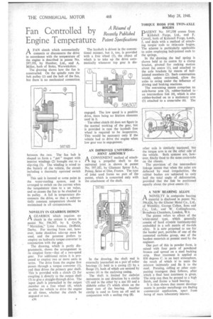
AFAN clutch which automatically connects or disconnects the drive in accordance with the temperature of the engine is described in patent No. 597,193, by Humber, Ltd., -and A. Miller, both of Stoke, Warwickshire.
The drawing shows how the fan is constructed. On the spindle runs the belt pulley (1) and the hub of the fan, hut there is no mechanical connection, between the two. The fan hub is shaped to form a " pot " magnet with interior windings (2) brought out to a slip-ring.(3). The winding is wired to the battery of the vehicle, the circuit including a thermally operated switch (4).
This unit is located at some point in the water-cooling system, and is arranged to switch on the current when the temperature rises to •a set value, and so causes the fan to be clutched to its pulley. A fall in temperature disconnects the drive, so that a substantially constant temperature should be maintained in all circumstances.
NOVELTY IN GEARBOX DESIGN
A GEARBOX Which requires no Clutch. in the system is shown in paient No. 596,307, by S. Grylis, " MaraziOn," Lime Avenue, Driffield, Derby. For starting from rest, however, some shocklcss take-up must be used, and the patentee prefers to employ an hydraulic torqtte converter in conjunction with the gear.
The drawing, which is partly diagrammatic, shows the arrangement in its simplest form—that of a two-speed gear. For additional ratios it is proposed to employ two or more units in series. The drive from the engine first passes through a torque converter (1), and then drives the primary gear shaft. This is provided with a clutch (2) for coupling it directly to the output shaft (3) to give a straight-through drive. The input shaft is journailed in the output ,member on a free wheel (4), which enables the vehicle to drive the engine at all times, whether the clutch be engaged or not.
A36 The layshaft is driven in the conventional manner, but it, too, is provided with a free wheel (5), the object of which is to take up the drive automatically whenever top gear is dis engaged. The low speed is a posittie drive, there being no ftiction elements used in it.
The other clutch (6) does not figure in the normal working of the gear, but is provided in case the layshaft free wheel is required to be inoperative. This would be necessary only If the vehicle had to drive the engine when low gear was in engagement.
AN IMPROVED UNIVERSALJOINT ASSEMBLY A CONVENIENT method of attach(1 ing a propeller shaft to the universal joint is shown in patent No. 597,182, by Glaenzer Spicer S.A., Poissy, Seine et Oise, France. The type of joint used forms no part of the patent, which is concerned only with the attachment of the shaft.
In the drawing, the shaft end is externally journalled on a pair of roller bearings (1) held in a casing .(2) by a flange (3), both of which are sectired by screws (4) in the enclosing casing.
The shaft is limited for endwise . .
movement in one direction by a main (5) and in the other by a nut (6) and a slidable collar (7) which abuts on the inner race of the bearing. Another circlip is used to form an oil seal in conjunction with a sealing ring (8).
TORQUE RODS FOR TWIN-AXLE BOGIES
DATENT No. 597,550 comes from
Kirkstall Forge, Ltd., and F. Cowell, both of Kirkstall Forge, Leeds, 5, and deals with a method of attaching torque rods to twin-axle bogies: The scheme is particularly applicable to axles employing ball-jointed ends to the springs. In the drawing the leaf spring is shown held at its centre by a clamp bracket, pivoted for rocking motion about the centre (1), and attached to the axle brackets by means of balljointed members (2). Such construction would, unless restrained, allow the axles to swing under the influence of driving and braking reactions.
The restraining means comprises an axle-borne arm (3), rubber-bushed to an intermediate link (4), which is also rubber-bushed on to a stationary arm (5) attached to a cross-tube (6). The other axle is similarly equipped, but the torque arm is on the other side of the vehicle. Both systems are, however, finally fixed to the same cross-tube on the chassis.
The provision " of the intermediate linkage means that when the axles are deflected by road irregularities, the rubber bushes are subjected to only half the total angle of deformation, provided that the link be positioned equally about the pivot centre (1).
A NEW BEARING ALLOY
ANOVELTY in composite bearing material is disclosed in patent No. 596,626, by the Glacier Metal Co., Ltd., of Wembley, George Cohen, Sons and Co., Ltd., and W. Collingbourne, Broadway Chambers, London, W.6.
The patent refers to alloys of the white-metal type, which generally consist of hard crystals (antimony-tin) embedded in a soft matrix of tin-rich alloy. It is now proposed to use for the harder part, particles of one of the cemented carbides group, one of the hardest materials at present used by the engineer.
One part of this in powder form, is mixed with four parts of powdered bronze and spread on a steel backing strip. Heat treatment is applied at 850 degrees C. in an inert atmosphere, the result of which is' to unite the mixture intimately and fix it to the steel. Pressing, rolling or other compacting treatment then follows, after which a final heat treatment is given. The strip can then be ground to a high finish, and forms a hard bearing.
It is thus shown that recent developments in powder metallurgy are finding commercial application, apart from being of mere laboratory interest.