


Pneumatic Tyre Built Mainly from Metal
Page 34
If you've noticed an error in this article please click here to report it so we can fix it.
A Resume of Patent Specifications that Have Recently Been Published
AE SCHEM for employing metal as the chief material of a pneumatic tyre forms the subject of patent No. 551,676, by R. W. Pringle, 40, Baines Avenue, Salisbury, Southern Rhodesia, P.O. Box 430. Perhaps a better
q■ description of the device would be to ' call it a pneumatically sprung wheel, which' employs an ordinary inner -tube for its resilient member.
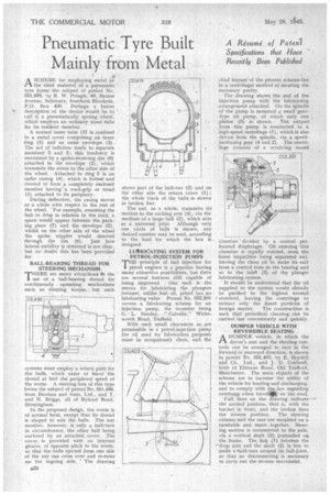
A normal inner tube (3) is confined in a metal cover comprising an inner ring (5) and an outer envelope (2). The act of inflation tends to separate member g 5 and 2; this tendency is restrained by a spoke-receiving rim (6) attached to the envelope (2), which transmits the stress to the other side of the wheel. Attached to ring 5 is an outer casing (4), which is bolted and riveted to form a completely enclosed member' having "a road-grip or tread (1) attached to its periphery.
During deflection, the casing moves as a whole' with respect to the rest of the wiheel. For example, assuming the hub to drop in relation to the road, a space would appear between the packing piece (7) and the envelope (2), whilst on the other side of the wheel the spoke nipples Would descend through the rim (6). Just how lateral stability is obtained is not clear, but no doubt this has been provided for.
BALL-BEARING THREAD FOR • STEERING MECHANISM .
THERE are many attractions In the use of . a ball-bearing thread for continuously operating mechanisms such as steering. worms. but such
systems must employ a return path for the halls, which enter or leave the thread at half the peripheral speed of the worm. A steering -box of this type forms the subject of patent No. 551,496, from Burman and Sons, Ltd., and T. and H. Briggs, all of Ryland Road, Birmingham.
In the proposed design, the worm is of normal form, except that its thread is .shaped to suit the balls. The nut member, however, is only a half-turn in circumference, the other half being enclosed by an attached cover. The cover is provided with an internal groove, of opposite pitch to the worm, so that the balls ejected from one side of the nut can cross over and re-enter on the ingoing side. ` The drawing shows part of the half-nut (2) and on the other side the return cover (1) ; the whole track of the balls is shown in broken line.
The nut, as a whole, transmits its motion to the rocking arm (4), via the medium of a large ball (3), which acts as a universal joint. Although only one circle of balls is shown, any desired number may be used, according to the load for which the box is designed.
LUISRIeATING SYSTEM FOR • PETROL-INJECTION PUMPS principle of fuel injection for petrol engines is a practice having many attractive possibilities, but there are several features still capable of being imptoved. • One such is the means for lubricating the pluegers because, unlike fuel oil, petrol has no lubricating value. Patent No. 552,201 covers a lubricating scheme for an injection pump, the inventor being G. L. Stanley, " Calvale," Wirksworth Road, Duffield.
With such small clearances as are permissible in a petrol-injection pump the oil used for lubrication purposes must be scrupulously clean, and the chief feature of the present scheme lies in a centrifugal method of securing the necessary purity.
' The drawing shows the end of the injection pump with the lubricating arrangement attached_ On the spindle of the pump is mounted a small gear-type oil pump, -of which only One pinion (5) is shown. The output from this pump is: conducted to a _high-speed centrifuge (1), which is also driven from the spindle, via a speedincreasing gear (4 and 2). The centri.fuge consists of a revolving vaned
chamber divided by a central perforated diaphragm. Oil entering this chamber is rapidly rotated, even the finest impurities being separated out, leaving the clean oil to make its exit from a centrol bore in the bearing and so to the inlet (3) of the plunger lubricating system.
It should be understood that the oil supplied to the system would already be purified to the highest normal standatd, leaving the centrifuge to extract only the finest particles of foreign matter. The construction is such that periodical cleaning; can be canied out conveniently and quickly.
DUMPER VEHICLE WITH REVERSIBLE SEATING
ADUMPER vehicle, in which the driver's seat and the steering controls cart be arranged to face in the forward or rearward direction, is shown in patent No. 551,403, by E. Boyden and Co., Ltd., and J. D. ColdweIl, both of Elsinore Road, Old Trafford, Manchester. The main objects of the scheme are to increase the utility of the vehicle for loading and discharging,'• and to comply with the law regarding
overhang when travel) on the road.
Full lines on the drawing indicate the normal position, that is, with the bucket in front, and the broken lines the reverse position. The steering column and the seat are mounted on a turntable and move . together, Steering motion is transmitted to the axle, via a vertical shaft (2) jonmalled ou the frame. The. link (1) between the --drop arm and the shaft (2) is free to make a-OialL4urn around its ball-joint, so that no disconnecting is necessary to carry out the reverse movement.