Strengthening Plates
Page 54

Page 55

Page 56

If you've noticed an error in this article please click here to report it so we can fix it.
in Body Construction
T R E NGTHOENINCI plates are essential for almost any class of woodbody framework, but they may also be utilized as one of the chief means for reducing weight if they be well designed and scientifically disposed. The modern bus body is a good example of this, for not only is it lighter than former patterns, but the improved forms of plate' used are in themselves lighter than the forgings previously employed.
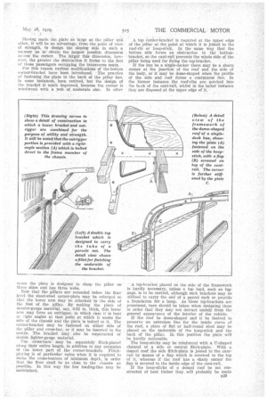
The most important corner-bracket is that situated at the junction of the side pillar and the cross-bearer of the bottom framework. The simplest way of strengthening this joint is to make a corner-plate which is fastened to the back of the pillar and to the top of the cross-bar. This bracket has to be constructed tck pattern, because the inside of the pillar is not at right angles to its cross-bar, but varies according to the turnunder or the, vertical contraction of the side of the body.
The plate may consist of a piece of half-round mild steel which is about 1,-k in. wide and in. thick, the substance being increased at the corner where the greatest strength is required. The defect of such a corner-plate is that the smaller dimension of the metal is vertical.
A more effective arrangement is to re-design the plate so that the larger measurement is vertical, in Which case it is fastened to the sides of the pillar and cross-bar respectively. It then forms approximately a right-angled triangle with one side projecting through the floor.
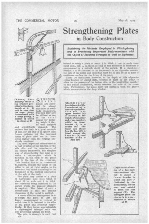
The gain in strength is such that B28 (Above) This drawing shows a top bracket provided with a turnbuckle at A. It will be seen that the lower fixing is combined with a lamp fitting, a section of which
is shown at B.
instead of using a plate of metal in. thick it can be made from sheet metal, say, 1-16in. thick, so long as this reduction in thickness is compensated by a suitable depth at the corner. If a sheet-steel bracket is to be fastened to the framework in an edge-wise manner_ the side of the pillar and cross-bar must be in line, so as to form a continuous surface for tile fixing of the plate.
There are limitations, however, to the depth of this edge-wis!?. corner-bracket or gusset-plate, because it must he cut away to allow for the passage of the bottom side, or the longitudinal member of the bottom framework, which connects the ends of the crossbars. Furthermore, the plate must not encroach upon the groove which accommodates the drop window.
Having made the plate as large as the pillar willallow, it will be an advantage, from the point of view of strength, to design the sloping side in such a Inc liner As to obtain the largest possible dimension' acmss' the corner. The larger this dimension however, the greater the obstruction it forms to the feet of those passengers occupying the :transverse seats.
For this reason various modifications of the bottom corner-bracket have been introduced: The practice of fastening. the plate to the back of the pillar has, in some instances, been revived, ' but the design of the bracket is Koch improved, because the corner is reinforced with a web of moderate size. In other cases the plate is designed to clasp the pillar on three sides and has three webs.
Now that the pillars are extended below the floor level the sheet-steel corner-plate may be enlarged .so that the lower arm may be attached to the side of the foot of the pillar. By making the plate of stouter-gauge material, say, 3-32 in. thick, this lower arm may form an outrigger, in which case it is bent at right angles at that point at which it meets the side of the chassis and the plate is bolted to it. The corner-bracket may be fastened on either side of the pillar and cross-bar, or it may be inserted in the centre. The bracket may also be constructed of double lighter-gauge material.
The cross-bars may -be separately. flitch-plated along their entire length, in addition to any extension of the lower, part of the corner-brackets. Flitchplating is of particular value when it is required to make the cross-bearers of minimum depth, in order that the floor shall be as close to the chassis as possible.. In this way the low loading-line may be maintained. • A top coraer-bracket is required at the upper edge of the pillar at the point at which it is joined to the roof-rib or hoop-stick. In the same way, that the bottom side forms an obstruction to the bottombracket, so the cant-rail prevents the whole side of the pillar being used for fixing the top-bracket.
If the bus be a single-decker there may be a sharp corner at the junction of the roof and the side of the body, or it may be dome-shaped when the profile of the side and roof forms a continuous line. In the former instance the roof-ribs are notched into the hack of the cant-rail, whilst in the latter instance they are disposed at the upper edge of it.
• A top-bracket placed on the side of the framework is hardly necessary, unless a top load, such as luggage, is to be carried, although such brackets may be utilized to carry the end of a parcel rack or provide a foundation for a lamp. As these top-brackets are prominent, 'care should be taken when designing them in order that they may not detract unduly from the general appearance of the interior of the vehicle.
If the roof be dome-shaped and it be desired to preserve an unbroken line for the inside curve of the roof, a plate of flat or halt-round steel may be placed on the underside of the hoop-stick and the back Of the pillar. In this position the plate will be hardly noticeable.
The hoop-sticks may be reinforced with a IT-shaped channel or a side or central flitch-plate. With a domed roof the side flitch-plate is joined to the ,cantrail by means of a flap which is screwed to the top of it, whereas if the roof has a sharp corner the flap is secured to the inside edge of the cant-rail.
If the hoop-sticks of a domed roof be not constructed of bent timber they, will probably be made B29
in three pieces and spliced at the ends. The flitchplate then helps to strengthen these splices.
As an alternative to the more conventional styles of top-bracket, it is suggested that the sloping side might consist of a turnbuckle with a right and lefthanded thread. Such a device provides a means for correcting any slight local deformation. In this instance, the side of a bus body is liable to "spread" a little in use. This could be corrected.
When the bus is a covered-top double-decker, corner-brackets are required at the floor level, which is the case with the lower saloon. These may be separate brackets or they may be combined with those situated at the top of the lower saloon. An examination of many upper saloons shows that sheetsteel corner-brackets fastened in an edge-wise manner are seldom employed for the roof of this part. A roof-rib of steel, however, not only stiffens the metal roof panel, but the rib has extensions or flaps at each end, which are fastened to the top cant-rails and no additional corner-brackets are therefore required.
The light method of construction, which is generally employed in the case of upper saloons is sometimes in contrast with the somewhat heavier timber and reinforcements used for a single-decker and, presuming that the former has been found satisfactory in service, there should be possibilities for a method of construction by means of which it would be possible to reduce the weight of a single-decker.


