


Number Three. Part Two.
Page 5
Page 6
Page 8
Page 9

If you've noticed an error in this article please click here to report it so we can fix it.
Although, as a rule, it is as well to 'let well alone," it needs care to ensure that all is always w11.
The first part of the present article coecluded, nil page 21-36, with the consideration of the carburetter and of a few White and l'oppe tips for using it properly. We may ne%r briefly consider the provisions for cooling the engine.. These, so far as the motor itself is coneertwd, are of normal design, employing an arnple•sized tubular radiator, a powerful fan, and a centrifugal pump. The main fire-pumping plant, which is part and parcel of the chassis, naturally affords a means by which i.his standard cooling equipment can be readily augmented, and, ars a matter of fact, an interesting :trran.gement, he which the lubricating oil which ie used in the engine is kept cool during long pumping runs, is embodied on this standard tire-engine chassis.
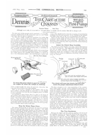
There is a shunt water-pipe through which water passes from the main delivery of the big centrifugal pump, niter eecountering a filter fixed to the nearside frame member—as shown in one er' the illustrations below. It is led through a spiral coil, Zubtleettaft
.1AieerSide fi-dwie Member'
which is fixed inside the main oil reservoir; thereafter the same pipe line continues up to the radiator.
There is, of Course, a strainer in the radiator filler in the usual pesition, and this should be kept clean, es also should the one in the pipe line from the mail: pumping plant to which wa have referred.
For draining in case of frost, there is a plug on the front of the radiator, and a drain cock to each of the pairs of cylinders. Similar provision IS made wherever notiessary on the Owynne pump. Front the back of No_ 4 eylinder there is a branch from the main water-circulating pipe, and this takes water to the jacketed induction pipe, and then on to the bottom of the carburetter, fitially entering the centre of the circulating pump. There is another drain cock on this pipe.
Keep the Water Pipes Clear.
The pump gland should, at intervals, be inspected and kept tight and the packing renewed when necessary. The short lengehe of flexible steam-pipe jointing an the suction pipe for the eireulaling pump, at the junction between the twn cylinder heads, and at the delivery conneuti.:m to the radiator. should be kept in god order end renewed if necessary : steam flexible pipinta of good quality should be used for this purpose.
Periodic cleaning of the whole of the circulating system is advisable, especially in eases where water of a doubtful quality has to be employed in emergency. The radiator itself may be well scoured with soda or some equally efficient cleaner; lb. of soda to each gallon of water is a useful mixture.
Before we leave the engine, we would point out that there are certain plugs on the cylinder castines which are merely put there to fill holes which are necessary in the foundry pm
ceases : they should not be removed, eecepting it be desired to ascertain, on very rare occasions, if any choking of the jackets has taken place due to the use of particularly had water.
There are also certain setscrew heads in the top half of the crankcase which might by chance excite the curiosity of a mechanic; these should also not be disturbed. The reason for their exietence is that they hold in position the various bearings for the camshafts.
Adjust the Clutch Stop Carefully.
The clutch is of the familiar COM) type, and in this instance it is linel with Ferodo. The engagement springs are external, and can be easily adjusted. There is a clutch stop which should also receive attention, care being taken to see that it effectively checks the revolution of the male member of the clutch when the latter is withdrawn sufficientJy whenever the gears ale: changed.
We drew attention to the intan-connection of the enuntershaft brake pedal and the clutch-withdrawal mechanism by means of a sketch, and this same illustration serves to demonstrate the manner in which the adjustment as between clutch pedal and clutch should be effected. When the clutch member has gene into the flywheel so far as to leave no play on the slrattel collar, as between clutch and brake, and when the travel of the former pedal brings it too near to the fontbnards, then is it time to screw up the short link Which is indicated in the illusteation: The clutelt-thrust ball bearing will want little attention, !yet it should be inspected with regularity, and when comfortably adjusted, it should be locked with a cheese-headed screw, which will be found provided for that purpose. It is easy to dismantle the whole ref this clutch gear by disconnecting the universal joint, which is coutigeous to it, and disconnecting the clutch springs. This should only be necessary when it is desired to refit the Ferode
The Two Gearboxes.
Between the clutch and the ordinary gearbox will be found the auxiliary gearbox, by which the drive to the main pumping plant is transmitted. There arernly two positions for these gears—in and out, the gear itself having a reduction ef about. I; to 1. There is a breather on the top of this ease to prevent the raising of any pressure in the box. Care should be taken to inspect from time to time the felt washers which are provided in connection with the ball bearings.
The ordinary change-speed gearbox is a well-tried unite and requires very little attention. Itehae four speeds, with the direct drive on fourth. Oecasimeil inspection of the shafts B15 Care of the Chassis (Dennis).
through the top cover, and assurance that none of the outside bolts and nuts have become loos; and that the covers for the ends of the eountershaft, with their locating setscrews, are in position, is advisable. These locating setscrews are intended to prevent the counterehaft from hunting; there should, under normal circumstances, be no thrust upon them. The felt washers provided in conjunction with the hall bearings may, at long intervals, want renewing. This should, however, aeldum be necessary on a machine with stall a low mileage record as a fire-engine.
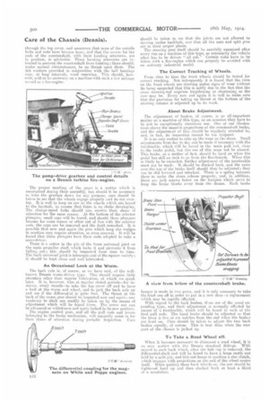
The proper meshing ef the gears is a matter which ie ascertained during their assembly, but should it be necessary to take the gearbox down fur any purple.; care should he taken to see that the wheels engage properly and do not overlap. It is well to keep an eve on the wheels which are keyed to the layshaft, to ensure that thee() is no shake developing. The change-speed forks should !Also receive their share if attention for the same reason. At the bottom of the selector plungers, Mail taps will be Found, and should these plungers become for some reason or other out of lino with the selector rods, the caps can be removed and the fault remedied. It is possible that now and again the pins which keep the wedges in position IMIV require attention, or even renewal. It will be found that these plungers have their ends adapted to take a screwdriver.
There is a cotter in the pin of the front universal joint on the main propeller shaft which locks it and prevents it from falling,_ out; this should he inspected from time to time. The back universal joint is telescopic and of the square variety ; it should be kept clean and well lubricated.
An Occasional Look at the Worm.
The back axle is, of course, as we have said, of the wellknown Dennis worm-driven type. This should require little attention other than regular lubrication, of which we speak later. It is, however, wise at regular stated periods—for instance, every month—to take the top cover off and to have a lnok at the worm and wheel, and to jack the hack axle up and see if the differential is quite freeThe thrust at the back of the Netitm gear should he inspected now and again ; any tendency to slack can readily he taken up by the means of adjustment which will be found there. The screw nut can be advanced or withdrawn and again locked in its new position.
The engine control gear, and all the pull rods and levers belonging to the brake mechanism, will naturally come in for their share of attention during periodic inspection. Care
should be taken to see that the joints are not, allowed to develop undue backlash, and that all the nuts and split pills are in their proper places.
The steering gear itself should be carefully examined after every rim on a machine of this type, as necessarily the vehicle often has to be driven " all out." Certain risks have to he taken with a fire-engine which can properly be avoided with an ordinary industrial model.
The Correct Tracking of Wheels.
From time to time the front wheels should be tested for correct tracking. Not infrequently it is found that the tires on the Front wheels are showing undue signs of wear without its being suspected that this is solely due to the fact that the cross steering-rod requires lengthening or shortening as the case may be. Every now and again it is well to make sure that the provision for taking up thrust at the bottom of the steering column is adjusted up to its work.
About Brake Adjustment.
The adjustment of brakes, of course, is an all-important matter on a machine of this type, as on occasion they have to be put to exceptionally strenuous use. One of our illustrations shows the massive proportions of the countershaft brake, and the ;adjustment of this should be regularly attended to, and, in fact, its inspection eatinot be too frequent.
It is an easy matter to take up the wear mi the shoes. Small arlhistments from day to day can be made if necessary with the turnbuckle, which will be found in the main pull rod, close to the brake pedal, but the use of this meet not he abused. This brake, as a matter of fact, should be hard on when the pedal has still an inch to go from the floorboard. When this is likely to be exceeded, further adjustment of the turnbuckle must not be made, It sheuld he sleeked back, and the cams over the top of the brake itself should then be adjusted ; they can be slid forward and relocked. There is a spring between them to make the shoes release properly, and, in addition, there are jack screws below on the hangers which serve to keep the brake blocks away from the drums. Each brake banger is made in two parte. and it is only necessary to take the hind one off in order to put in a new shoe—a replacement which may be rapidly effected.
With regard to the back brakes, these are of the usual expanding type, and their adjustment is nermally effected by means of e turnbuckle, which will be found in each of the final pull rods. The hand brake should be adjusted so that the lever is five or six notches from the end when the brakes are herd on. Care should be taken to adjust the two back brakes equally, of course. This is best done when the rear part of the chassis is jacked up.
To Take a Road Wheel off.
When it becomes necessary to dismount ii road wheel, it is an easy matter with theDeunie standard fittings. With reeard to each back wheel, after the hub cap is removed, the differential-shaft end will be found to have a. large castle nut held by a split pin, amid this nut keeps in position a star clutch, which engages with projections on the end of the wheel centre itself. When putting these bark wheals on. the nut should be light-sued bard up and then slacked back at least a third of a revolution. With regard to the front wheels, these are provided with D washers, and they should be pulled up tight when the wheels are being replaced. The stub axles will require very little attention. The stub pins themselves are fixtures, held in position by cotter pies; these letter should be looked to from time to time, to ensure that they are properly in positiou.
Now, although the purely pumping part of the mechanism of this typical machine appears to the uninitiated, at first sight, to be a little complicated, as a matter of fact it has been reduced, by continued trial and experiment, to a very simple form indeed, with the result that this part of the machinery requires only reasonable care and attention. The general lay-out uf these parts is quite evident in the various illustrations which we include with the present article.
When the Pump is Working.
The auxiliary gearbox we have already meetionedThe universal joint, by which cenneetion is made to the pump-driving shaft, will look after itself if it be kept clean and hibricated. The pump itself is of the multi-stage turbine type, and there are no valves or sliding parts to get out of order. The great thing is to keep the lubricators well tilled arid screwed down slightly at short intervals while the pump is hard it work. The thrust bearing right at the end of the pump should come in for special care under like circumstances. Light machine oil is eecommended at this point, and this should be drained off from time to time, and clean, fresh oil put in its place. This bearing must be watched with the usual care, M order to insure that no end play develops on the pump spindle, At the front and back of the pump chamber proper there are stuffing-bexes, and these must he kept well packed and carefully adjusted. The bearings inside the turbine pump depend upon water for their lubrication, and it is, therefore, obviouely important that the pump should never be run dry. There is an arrengement by which a water seal is maintained on the back bearing; it is a fairly accurate guide as to its efficiency if water be found just to be dripping from the gland. There are, of cot's-se, drain cocks on to the main casting which Can be opened when it is necessary to insure that all water has left the pump body. In order to reduce the whole thrust pressure arising from the pimp when it is at full work, a balance pipe is laid from the main suction Mkt to A point on the casing of the finalstage impellor. These balance pipes, of course, need never be disturbed, excepting if it be desired LO insure that they are not choked. ilv.ent ssppe rernino gears 4. ,sec, pro,* CAM
'tee
If the Pump be Taken to Bits.
On occasion it may be considered desirable to dismantle the whole pump, but this is an operation of no difficulty. A screwed collar holds the impellers in position on the pump .spindle, and it must be remembered that this collar, in addition to being pinned, is screwed left-handed; this is important to bear in mind, so that no attempts may be made to force it in the ordinary direction.
When taking down the pump, all the parts will be found to be carefully marked, but, in addition, great care must be exercised, in order to insure that re-assembly may be made in exactly the same order, and with all the packing and bearings in their correct positions.
This is a good opportunity to examine the impellors and water jackets, to see. that 110 foreign matter is lodged in them, a contingency which will only arise when the pump happens to have been used without a strainer. If the pump be used with hydrants, dirt, stones and other foreign matter may lodge between the plates without doing any harm. Anything that passes through the holes in the standard copper strainer will pass through the Dennis turbine pump, and stance and mud will not interfere with its effiviency of W orki rig. Suction couplings must be kept tight, and the leather washers greased ready to make good joints.
Some Notes about the Air Pumps.
\V tin eegard to the air-pump priming set, which is mounted over the front end of the turbine pump, this is driven through a spur-gear pair by means of a metal cone clutch fixed to the pump spindle. This clutch is operated by a lever carried at the back of the merle an the same quadrant as the throttle lever. Operation of this clutch also moves the valve in the vacuum pipe between the air and water pump. When the -clutch is in, this valve is opened to allow air to be exhausted from the pomp. Similarly, when the clutch is out, it is closed. It is important that the air rump shall not be run too fast; about 700 r.p.m. is found to be sufficient. Higher speeds give no better results. The air pumps can be tested from time to time by screwing the blank cap on to the suction of the main turbine, and then running the air pumps until the vacuum gauge registers 24 ins_ If the engine then be stepped it will be possible to see if the vacuum is held, or if any of the joints aro letting air past.
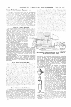
It is now necessary for us briefly to summarize the provisions for lubrication throughout this chassis, and to indicate how and when they should be used.
We Imes expended a great deal nf time and trouble in the preparation of the adequate lubricating chart which is part and parcel of this article. The periodic intervals which are indicated thereon as being desirable, in order to insure that all ports have their adequate supply of lubricant, have been considered and arrived at on the bases of the averoge working performance of an engine in a fairly busy station. Common sense and experience will do much to indicate if these intervals may be modified iii either direction with advantage.
First of all, briefly, with regard to the engine. We have produced a separate drawing, which illustrates the very complete provision which is made for the lubrication of the
prime mover, and this system is not without its interesting features. A duplex pump is situated immediately bel6w the sump in the bottom half of the crank chamber, and the lower half of this draws oil from the reservoir and delivers it through a filter into the bottom half of the bearing to the front crankshaft journal. Then, by an ingenious arrangement of drilling, the latter is made to act as a distributor between the various main bearings of the engine. Our diagram renders this quite clear.
An air bottle is inserted in the pipe line, which also has the pressure gauge attached to it. There is, in addition, a spring-loaded valve inserted, in order to insure regular indications on the gauge, which latter, by the way, is situated on the dashboard. A shunt from one of these pipes take oil to the timing gearcase and to the thrust provision of the centrifugal water-circulating pump. Oil thus delivered to the main bearings finds its way down into the eraekpit and into the troughs cast in it, one below each big end.
1111117—A-7..._ allt(ffeir The top half of the duplex pump returns surplus oil from this sump into the reservoir again through a filter. Au unusual provision, which we have already mentioned, is the method of keeping the u31 in this reservoir cool during such time as the engine is engaged on long piimpiug runs. A copper coil in the tank allows water from the nia.in turbine delivery pipe to circulate through the tank and keep the oil cool. A clack valve prevents water from the radiator running along this pipe hack to the pump, end it also prevents the air pump when starting up the turbine front drawing wetter from the radiator, instead of air from the main suction.
It will be noticed that there is an air vent on the top of the oil reservoir. Beneath the engine water pump there is a little hole, which should be kept clear, to allow waste grease and water to get away and to prevent water's getting into the timing-gear easing. The oil reservoir should never be kept more' than three-quarters fall. Oil for Gearboxes and Back-axle.
With regard to gearboxes, the special one for the pump drive should have sufficient mixture of Vacuum C oil and grease for the wheels just to pick it up when they are running. In the main gearbox, lubricant should be put in sufficiently to reach to the bottom of the gearbox shafts. Any good thick ,rmar oil and grease, mixed in equal parts, may well be used for both these boxes.
With regard to the rear axle, the worm gear is intended to run entirely in oil, but as a rule it will be found that it will be sufficient to add a pint of oil and one pound of grease re. ery three or four months, according to the work dune.
With regard to all the greasers and oil caps which arc clearly marked on our page illustration, these should be attended to at least as frequently as we suggest. Special care should he taken that when the main turbine pump is hard at work, the large greasers should constantly be given slight turns.
We may perhaps summarize for convenience the various periodic lubrication duties.
DAILY.—Screw up greasers on all spring shackle pins ; go round all brake connections with an oil-can, as also various steering-gear joints, brake-control details, and clutch-control and engine-control joints; turn greasers on the road-wheel hub caps.
Owing to the fact that a fire-engine's mileage is such a low one, the intervals at which many of the lubrication provisions should be operated, as shown on our full-page lubricating diagram, are necessarily longer than would be correct if the machine were doing the mileage of an ordinary lorry. Such operations, however, depend entirely upon the number of journeys the machine is making on the average. Mau:yea the items which we have put down to be attended to weekly are those which are seen to daily on the ordinary lorry.
WEIK1.Y.—Oil the starting-handle spindle ; a drop or two of oil on the engine-control levers; turn the greasers on the universal joints on the main driving shaft. The gearbox should be inspected at least, weekly, to see that it has a sufficient quantity of the mixture of oil and grease; care should be taken not to put too much in, and the oil and grease ntay be mixed in equal parts for satisfactory service; the mirture should reach up to the bottom of the gearbox shafts. It is probable that this will only need attention at mueh longer intervals, but that all depends, of course, upon the mileage the machine is called upon to do. The greasers on the inside of the back hubs should be turned at intervals of not less than a week. All the steering-rod ends should also have attention at this interval. The steering box may require a little additional oil—two oilers are provided for this purpose. The pedal-shaft greasers may be turned at about this interval, and oil should be employed on the change-speed mechanism and various brake-hanger joints which are indicated. The shaft for the countershaft brake should be greased at least once a week.
Operations which are sufficiently cared for if they take place at intervals of about a month, on a chassis like this, are the greasing of the spring leaves, and the putting of a drop of oil into the cup at the back of the magneto.
There is, of course, no absolutely hard and fast rule in respect of these intervals, especially in a type of machine which varies so greatly with regard to the intensity of its service. We, however, intend our diagram to serve as a useful basis upon which to work, and trust it will be found of assistance in that respect.
It only remains for us to ask those who have Dennis fireengines in their charge to treat them intelligently and with some endeavour to appreciate the fact that the makers, while they have produced a machine which normally will give the minimum of trouble, are dependent for the best molts on the thoroughness and conscientiousness with which those who have it in their charge take "care of the chassis."