


Patents Completed.
Page 20
If you've noticed an error in this article please click here to report it so we can fix it.
DISTANCE INDICATING APPARATU.S.—Rhodes.—No, 7,688, dated 2nd April, 1007.—This invention relates to a variable speed device for a distance-indicating apparatus whereby a standard indicator can be used on vehicles having road wheels of varying sizes. The usual indicating mechanism (1) is supported by a bracket (2) within the casing (3). The spindle (4) of the indicating mechanism carries, at its lower end, a friction disc (9) extending through the casing (3). A bracket (5), in which is formed the bearing (6) of the driving shaft (7), is secured to the casing (3). The driving shaft carries a friction disc (8) and, between this disc and the disc (9), carried by the spindle (1), is a roller (10) loosely mounted on an adjustable spindle (11) between collars (10x). The discs (8, 9) and the roller (10) are kept in frictional con tact by means of a spiral spring (13) interposed between the bracket (2) and the friction disc (9). It will be seen that, by adjusting the position of the intermediate roller (10) between the faces of the two disc wheels (8, 9), a variable drive is obtained.
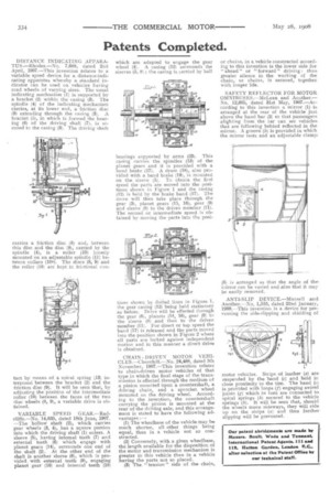
VARIABLE SPEED GEAR.--Radcliffe.—No. 14,035, dated 18th June, 1907. —The hollow shaft (2), which carries gear wheels (3, 4), has a square portion into which the driving shaft (1) enters. A sleeve (5), having internal teeth (7) and external teeth (6) which engage with planet gears (14), surrounds one end of the shaft (2). At the other end of the shaft is another sleeve (8), which is provided with external teeth (9), engaging planet gear (16) and internal teeth (10) which are adapted to engage the gear wheel (4). A casing (12) surrounds the sleeves (5, 8) ; the casing is carried by ball
bearings supported by arms (23). This casing carries the spindles (13) of the planet gears and it is provided with a band brake (17). A drum (18), also provided with a band brake (19), is mounted on the sleeve (5). To obtain the first speed the parts are moved into the positions shown in Figure 1 and the casing 021 is held by the brake band (17). The drive will then take place through the gear (3), planet gears (15, 16), gear (9) and sleeve (8) to the driven member (11). The second or intermediate speed is obtained by moving the parts into the posi
tions shown by dotted lines in Figure 1, the gear casing (12) being held stationary as before. Drive will be effected through the gear (6), planets (14, 16), gear (9) to the sleeve (8) and thus to the driven member (11). For direct or top speed the band (17) is released and the parts moved into the position shown in Figure 2 where all parts are locked against independent motion and in this manner a direct drive is obtained.
CHAIN DRIVEN MOTOR VEHICLES.—Churchill.—No. 24,488, dated 5th
November, 1907.—This invention relates to chain-driven motor vehicles of that type in which the final stage of the transmission is effected through the medium of a pinion mounted upon a countershaft, a driving chain, and a sprocket wheel mounted on the driving wheel. According to the invention, the countershaft carrying the pinion is mounted at the rear of the driving axle, and this arrangement is stated to have the following advantages : (1) The wheelbase of the vehicle may be much shorter, all other things being equal, than in a vehicle not so constructed.
(2) Conversely, with a given wheelbase, the length available for the disposition of the motor and transmission mechanism is greater in this vehicle than in a vehicle having the parts not so placed. (3) The " tension " side of the chain, or chains, in a vehicle constructed according to this invention is the lower side for " ahead " or "forward" driving thusgreater silence in the working of the chain, or chains, is secured, together. with longer life.
SAFETY REFLECTOR FOR MOTOR OMNTBUSES.—MeLean and Another.— No. 12,605, dated 31st May, 3907.—According to this invention a mirror (1) is arranged at the rear of the vehicle just above the hand bar (2) so that passengers alighting from the car can see vehicles, that are following behind reflected in the mirror. A groove (5) is provided in which the mirror rests and an adjustable clamp (6) is arranged so that the angle of the mirror can be varied and also that it may be easily removed.
ANTI-SLIP DEVICE.—Mansell and Another.—No, 1,510, dated 22nd January, 1008.—This invention is a device for preventing the side-slipping and skidding of
motor vehicles. Strips of leather (a) are suspended by the band (c) and held in close proximity to the tire. The band (a) is provided with loops (f) engaging swivel joints (g) which in turn are connected to spiral springs (h) secured to the vehicle springs (I). It will be seen that, should the wheels move sideways, they will ride up on the strips (a) and thus further slipping will be prevented.