


A Magnetically Operated Gearbox
Page 58
If you've noticed an error in this article please click here to report it so we can fix it.
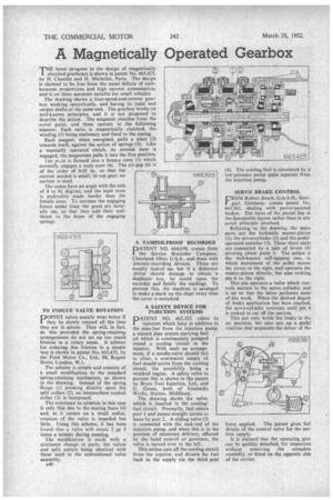
THE latest progress in the design of magnetically clutched gearboxes is shown in patent No. 665,425, by H. Chatelet and H. Michellet, Paris, The design is claimed to be free from the usual defects of cumbersome proportions and high current consumption, and is on these accounts suitable for small vehicles.
The drawing shows a four-speed-and-reverse gearbox work ing epicyclically, and having its input and output shafts at the same end. The gearbox works on well-known principles, and it is not proposed to describe the action. The magnetic clutches form the novel point, and these operate in the following manner: Each ratio is magnetically clutched, the winding (1) being stationary and fixed to the casing. Each magnet, when energized, pulls a plate (2) towards itself, against the action of springs (3). Like a manually operated clutch, its normal state is engaged; the magnetism pulls it into the free position. he pti.te is formed into a fernate cone (5) which normally engages a male cone (4). The air-gap (6) is of the order of 0.02 in., so that the current needed is small; in top gear, no current is used.
The cones have an angle with the axis of 8 to 8i degrees, and the male cone is preferably made harder than the female cone. To increase the engaging forces under load, the gears are helically cut, so that they add their endthrust to the force of the engaging springs.
TO INDUCE VALVE ROTATION
POPPET valves usually wear better if they be slowly rotated all the time they are in action. They will, in fact, do this, provided the spring-retaining arrangements do not set up too much friction in a rotary sense. A scheme for reducing this friction in a simple way is shown in patent No. 665,435, by the Ford Motor Co., Ltd., 88, Regent Street, London, W.1.
The scheme is simple and consists of a small modification to the standard 'spring-retaining mechanism, as shown in the drawing. Instead of the spring flange (1) pressing directly upon the split collars (2), an intermediate conical collar (3) is interposed.
The resistance to rotation in this case is only that due to the mating faces (4) and, as it occurs on a small radius, rotation of the valve is impeded but little. Using this scheme, it has been found that a valve will rotate 2 or 3 times a minute during running.
The modification is made with a minimum change in parts, the valves and split cotters being identical with those used in the conventional valve assembly_ A40
A TAMPER-PROOF RECORDER
PATENT NO. 664,699, comes from the Service Recorder Company, Cleveland, Ohio, U.S.A., and deals with journey-recording devices. These are usually locked up, but if a dishonest driver should manage to obtain a duplicate key, he could open the recorder and falsify the readings. To prevent this, the machine is arranged to make a mark on the chart every time the cover is unlocked.
A SAFETY .DEVICE FOR INJECTION SYSTEMS PATENT NO. 665,325, refers to injectors which have in addition to the pipe-line from the injection pump, a second pipe system carrying fuel oil which is continuously pumped round a cooling circuit in the injector. With such an arrangement, if a needle-valve should fail to close, a continuous supply of fuel would arrive from the cooling circuit, the possibility being a wrecked engine. A safety valve to prevent this is shown in the patent by Bryce Fuel Injection, Ltd., and G. Green, both of Iron barks Works, Staines, Middlesex.
The drawing shows the valve, which is inserted in the coolingfuel circuit. Normally, fuel enters port 1 and passes-straight across to leave by port 2. A sliding valve (3)
is connected with the rack-rod of the injection pump, and when this is in the position of minimum delivery, effected by the hand control or governor, the valve is moved over to the left.
This action cuts off the cooling circuit from the injector, and diverts the fuel back to the supply via the third port (4). The cooling fuel is circulated by a low-pressure pump quite separate from the injection pump.
SERVO BRAKE CONTROL
VROM Robert Bosch, G.m.b.H., StuttI gart, Germany, comes patent No: 665,561, dealing with power-assisted brakes. The basis of the. patent lies in the favourable layout rather than in any novel principle involved.
Referring to the drawing, the main parts are the hydraulic master-piston (1), the servo-cylinder (2) and the pedaloperated member (3). These three units are connected by a pair of levers (4) pivoting about point 5. The action is the well-known self-lapping one, in which movement of the pedal moves the levers to the right, and operates the master-piston directly, but also rocking pin 6 to the right.
This pin operates a valve which controls suction to the servo cylinder, and is set so that the latter performs most of the work. When the desired degree of brake application has been reached, the servo-cylinder overruns until pin 6 is rocked to cut off the suction.
This not only holds the brake in the set position, but also sets up a pedal reaction that acquaints the driver of the force applied. The patent gives full details of the control valve for the suction supply.
It is claimed that the operating gear can be quickly detached, for inspection without removing the complete assembly, or fitted on the opposite side of the carrier.