


Hints on Servicing a
Page 48
Page 49
If you've noticed an error in this article please click here to report it so we can fix it.
TRACTO] 4AGNETO
Careful Attention to the Magneto Will Do Much to Maintain Electrical Efficiency in Farm Tractors. This Article Deals With the Lucas GT4 Equipment
AMAGNETO fitted to a fourcylindered engine running at 1,000 r.p.m. produces 2,000 spzrks a minute, or 33 every second. These sparks have to be distributed between the four sparking plugs, and each spark should be of sufficient intensity to jump across a gap which is under pressure. To do this efficiently, for long periods, it is essential that every part of the magneto be regularly serviced, and unless this work be done well, trouble is bound to result.
The two common enemies of electrical efficiency are damp and dirt, for dampness provides a ready path along which the current will escape before it can do its work, and dirt hinders flow and reduces the current reaching the sparking plugs.
Cleanliness First The first thing to do when checking over the ignition system on a tractor is to see that the magneto, high-tension leads, plug insulators and the switch and wiring are dry, and that all contacts are clean and secure. The magneto is often blamed when the fault lies elsewhere.
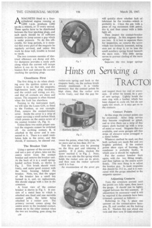
Turning to the instrument itself, we will take the Lucas GJ4, as fitted to the Fordson, as our example. First, remove the contact-breaker cover. Inside the cover is a strip of copper carrying a small carbon block which presses on the centre screw of the contact breaker (A, Fig. 1).
Unless these two make proper contact the magneto cannot be switched off. An earthing contact, B, is attached to the cover and is connected to A. There is a small ventilation hole in the cover, and this should, if necessary, be cleaned out.
The Breaker Unit Using a spinner of the correct size, and not a pair of pliers, take out the centre screw from the contact breaker and remove the breaker unit. At the back of it is a small springloaded carbon brush, as shown in Fit„. 2. This brush should work freely, and make good contact with the brass housing behind the breaker. Note, too, that the spigot of the breaker has a small key formed in it, and, on replacement, this should engage with a slot in the armature.
A front view of the contact breaker is shown in Fig. 3. It consists of a metal base to which is attached one fixed and one movable contact point, the latter being attached to a rocker arm. The primary current comes along the centre screw to the insulated contact, passes on to the other contact when the two are touching, goes along the rocker-arm spring and back to the magneto body, via the carbon brush already mentioned. It is vitally necessary that the contact points be kept clean, that the rocker arm wcrks freely, and that the gap be
tween the points, when fully open, be no more and no less than .012 in.
Test the rocker arm by pressing on the fibre pad and releasing it quickly. If it sticks, slacken the screw marked C in Fig. 2. Next, slide to one side the flat spring which holds the rocker arm on its pivot, and then ease the rocker upwards until it is free.
An examination of the pivot pin will quickly show whether lack of lubricant be the trouble—which it probably is. Clean the pin With a ' piece of rag moistened with petrol, dry it, and then smear with a little fight oil.
Then inspect the contact-breaker main springs. In this magneto there are two. It is best to separate them for inspection, so remove the screw which was formerly loosened, taking care not to drop it, or to lose the small auxiliary spring found beneath the main ones. This little spring serves to prevent chafing of the main springs.
Separate the two larger springs
and inspect them for rust or corrosion. If either be tound, fit a pair of new springs. Lightly brush the cam ring with a feather which has been dipped in cycle oil, but do not apply too much, or it may get on to the contacts. • Contact Points At this stage the contact points can be examined. After long service they become roughened or pitted,. and to trim them use a strip of fine emery cloth backed up with a strip of metal or wood. Magneto files are available, and some garages sell thin strips of abrasive stone arranged in a metal holder.
Whatever method be used, see that both surfaces are made flat and are brightly polished. If the contact points show signs of burning, the condenser is probably faulty, in which case it should be replaced.
Put the contact breaker back again, with the key fitting snugly, and then tighten up the centre screw firmly. The next thing is to adjust the breaker gap. In most magnetos this should be .012 in., and it is measured with the gauge attached to the magneto spanner.
Adjusting Contacts Turn the armature around until the points are fully open, then insert the gauge. It should just be lightly nipped between the two contacts. If adjustment be necessary—and it will be required if the contacts have been trimmed—proceed as follows:— Referring to Fig. 3, place one spanner on the contact-screw hexagon, D, and another on the locking nut, E. Slacken this nut about one turn and then turn D (anti-clockwise
to close the gap) until the feeler is lightly held, then lock the contact in this position by tightening nut E.
Now revolve the armature until another lobe of the cam opens the points, and check again. The gap should be the same, but if it be not, because of a worn cam, adjust so that the average gap is between .011 in. and .013 in Should this be impossible, the cam is worn and a new on should be fitted.
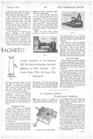
The next step is to check the condenser, although, if the contact points were found to be comparatively clean, it is an indication that it is working properly. On polar-inductor magnetos the condenser can easily be detached and tested with mains current, as shown in Fig. 4.
When the current is switched on, the lamp will light when the two free ends of the wires are touched together. In testing the condenser, with a lead on each terminal of the unit the lamp should not light. Should it do so there is a fault.
It is, of course, the function of a condenser to hold an electrical charge for a short period, and the same apparatus will suffice for this test, too Put the condenser on a piece of glass or dry wood, and place the two leads on the terminals, as before.
Condenser Tests
There should now be sufficient current in the condenser to produce a snappy spark when the two terminals are bridged with a screwdriver or other Metal object. If there be no spark, then the condenser is faulty and should be replaced. Either a.c. or d.c. mains current can be used for these tests.
Turning to the high-tension side of the magneto, remove the distributor cover and wipe it carefully inside and outside, and check the security of the high-tension wires. If the distributor Segments be dirty, rub them lightly with a fine glass paper. '• In the front of the distributor cover is a gauze window to serve as a ventilator. Clean it with a brush dipped in petrol. Lack of ventilation results in corrosion of the segments and a weak spark. Then inspect the rotor; the brass arm should be clean, particularly on the edge from which the current jumps to the distributor segments.
There are three other carbon brushes to inspect, two of them on the pick-up To reach the pick-up, take out the three screws holding the aluminium cover which lies between the impulse starter and the magnet, and take off the cover. It will be noticed that this has a grease-impregnated felt insertion strip to keep out moisture.
The pick-up is shown in position in Fig. 5, and to remove it bend back the locking Os, and take out the two screws. Lift it out carefully, otherwise the lower brush may be damaged. Fig. 6 shows the pick-up, with its two carbon brushes. See that these are not unduly worn, and that they slide easily in their guides.
The Last Stage
The last brush to receive attention is found underneath the magneto, between the two front securing bolts. Unscrew the brush holder and check the brush for wear and freeness in its holder.
The rotor pencil, which conveys the high-tension current from the pick-up to the distributor, runs in a bearing which is lubricated via the small flap on the top of the magneto. Lift the flap and add a few drops of thin oil. Oil should not be added through the small round hole which is provided to let out air, as the oil goes into the bearing through the large slotted hole.