


Patents Completed.
Page 24
If you've noticed an error in this article please click here to report it so we can fix it.
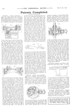
STEERING FORE CARRIAGE. Latil.-No. 4,512, dated 23rd February, 1906.-The explosion motor (1) is arranged transversely as shown in Fig. 1 ; starting is effected by means of the extremity (2) of the crankshaft ; 3 is the flywheel, the part (4) of which is arranged for the reception
of the clutch cone (5) covered with leather. In order that the clutch operating gear may occupy the minimum of space, the following special arrangement is adopted : the pedal (6, Figs. 1 and 3) acts by the intermediary of the connecting rod (7) on a nut (8) held between two cheeks (nut shown in the drawing) fixed to the chassis or frame? in such a manner that the nut may be given a movement of rotation without displacement parallel with the shaft. This nut (8) rotates on a screw (9) mounted loosely on a sleeve (29) with a square hole sliding on the shaft (11) and riveted to the clutch cone (5) ; the shaft (11) is not solid with the crankshaft of the motor. The screw (9) is internally provided, on the side opposite to the clutch cone, with grooves (10), sliding at 30 in parts fixed for that purpose, thereby preventing this screw from rotating. It will be obvious that, if a movement of rotation in either direction be given to the nut (8), the screw (9) will be displaced parallel with the
shaft, carrying with it the sleeve (29) and the cone (5), thereby producing engagement or disengagement. The nut (8) (Fig. 3) carries a series of holes (22), permitting of regulating the clutch in a simple manner ; if the leather on the cone is worn, so that driving is not properly effected, the shaft (23) is withdrawn ; the nut is rotated by the amount required, then the connecting rod is fixed in another hole (22), and the adjustment of the clutch is complete. The position of engagement corresponds to the raised pedal position (37.) so that the pressure required for preventing slipping of the leather is obtained from a powerful spring (21) acting upon the nut (8). The square shaft (11, Fig. 11 in one piece with 12, drives the gear wheel (13) which, either directly, or by the intermediate wheel (32), drives the gear wheel (14, Figs, 1 and 2) of the change-speed gear. A square shaft (16, Fig. 2) carrying a sliding train (15), admits of three or four forward speeds and a reverse ; at the extremity of this shaft (16) there is fixed a brake drum (17), and a square box (19) in which the head (331 of the shaft (18) is
jointed and driven, transmitting the movement to the differential through the cardan joint (20). The pinion (34), solid with a fork of the cardan joint, drives the gear wheel (35) fixed to the crown carrying the satellite pinions of the differential gear; the whole is contained in a gearcase (36), the satellite pinions (41) drive the wheels (39, 40) solid with the shafts (37, 38), which, being jointed at 43, drive, by means of the pinions (45), the gear wheels (46) fixed upon the wheels. The joint consists of a sphere (43) of tempered steel provided . with two deep circular grooves formed at an agle of 900, as shown in Figs. 1, 2, and 3, two parts (42, 44) engage upon either side in these grooves so that the power is transmitted from one length of the shaft to the other so long as the summit of the angle formed by the axes of. these lengths coincides with the centre of the sphere, as is the case here. where the mounting is such, that the centre of the sphere (43) is situated in line with the axis of the steering pivot (54) ; the position of these axes is obtained, on the one hand, by the part (48) which firmly supports the part (42) of the joint and the fork of the pivot, and on the other hand, by the gearcase (50) which supports the part (44) and the pivot (54). The steering rod (65), maintained by the support (64), is placed entirely in front of the vehicle (Fig. 1) it acts by means of a screw and a nut upon a transmission link (66). The lever (67), by an intermediary of the connecting rod (68) pivoted at 67 and 69, acts upon a double lever (70) fixed to the steering pivot of one of the wheels. The other steering pivot carries a simple lever (74), connected to the first by a connecting rod (731 pivoted at 71 and 72. This arrangement permits of bringing the useful load of the vehicle close to the front axle, thereby imparting more adhesion to the driving wheels, and this renders it possible to reduce the wheelbase, which facilitates the turning of the vehicle.
CHANGE SPEED MECHANISM.Renaux.-No. 26,658a, dated 3rd March, 1906.-This invention belongs to the type of gear wherein a rotatable member (1) is employed carrying several bevel wheels which may be separately engaged with the driving shaft (26), and a driven member (16). Each of the bevel wheels (1, 2, 3, 4, 5) is carried on a separate axle hinged to the central member (1), and each axle has an arm which engages a cam-groove (33) on a fixed part of the casing (10). The driving shaft (26) is movable endwise and has a clutch member (31), at one end. adapted to engage a corresponding member (15), with which each of the bevel wheels is provided. The block (30) carrying the clutch-part (31) also carries a stud (34) which extends beyond the casing of the gear and carries a pin (35) which enters the casing. The member (A) has a series of peripheral orifices corresponding to the various axles and adapted to register with the pin (35), so that this pin may lock the member in position for any one of the gears. The member (1) is rotated by a rack (37) and pinion (38) ; the axle (26) being withdrawn in the meantime. As the member is rotated, the cam-groove will move the axles of the various bevel. wheels, and when these have been brought into such position that the desired bevel wheel, say 4, has been brought into engagement with a corresponding series of teeth on the driven member (16), the driving shaft (26) is advanced to engage the clutch parts (31, 15) and the pin (35) simultaneously locks the member (1) against further rotary movement. The member (1) also carries two bevel wheels (6, 7) which mesh with each other and swing upon a single pivot, whereby reversing may be effected.
BURNER.-Sheppee and Others.-No. 6,570, dated 19th March, 1906.-To obtain a burner that shall not light back whether a large amount of vapour or a small amount is passing through it, the nozzle (F) is arranged to discharge into a conduit having a converging mouth (a), and, opposed to this conduit, is a baffle (E). The baffle is mounted in a combustion chamber (B) having a perforated top (D). With such an arrangement an even feed of the vapour takes place whether a large or small quantity is passing through the burner, and back-lighting is avoided.
RUBBER C OM PO SITION.-Jackson. -No. 2,791, dated 5th February, 1906.To prevent side-slipping it is proposed to incorporate powdered slag, such as the refuse from blast furnaces, in the rubber whereof the tires are composed.