


Petrol Motor Omnibuses.
Page 19
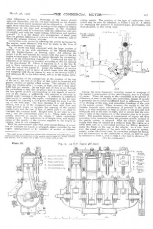
Page 20
Page 21
Page 22
Page 23
If you've noticed an error in this article please click here to report it so we can fix it.
By W. Worby Beaumont, M.I.Mech.E., M. Inst. C.E.,
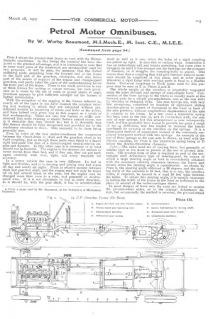
Plate 4 shows the pressed-steel frame as used with the Mimes. Daimler omnibuses. In this design the material has been disposed to the greatest advantage, and it is interesting to note that m some ways parts of the framework are satisfactorily used for two purposes: It will be seen, for instance, that the dished stiffening plate, extending from the forward end of the frame to the back end of the gear-box, reinforces, and also forms part of the means of support of the engine and change-speed gear-box, and partly takes the place of the undersheathing below the front part of the frame. There is not much provision in any of these frames for racking or corner stresses, but such provision as is made by the use of webb or gusset plates at angle junctions appears to give sufficient strength for the frames of lighter automobiles.
With the exception of the sagging of the frames referred to, nearly all of the types in use have resisted the constant twisting and working to which they are subjected without pronounced trouble by loosening of rivets and bolts at the joints, and have indeed only given way in this respect as a result of bad workmanship. There are very few frames so stay constructed that some twisting or elastic flexure cannot occur, nor is it desirable that they should be; but it is desirable that this flexure should be fully recognised and provided for in the machinery attached to them. This necessity is far from being generally met.
Even in some of the best motor-omnibuses the connection between the clutch-drum or shaft and the gear-box shaft is by rigid coupling, just as though these parts were fitted to a heavy rigid bed-plate like that of a direct-coupled central-station engine and dynamo. In this latter case it is necessary or at least should not be harmful. The engine or the dynamo are seldom or never moved from their bed, and if they are, they are put back again carefully with time, light, and every requisite for accuracy.
In a motor vehicle the case is very different. Its bed is light and flexible, and it is dancing and jolting over bad roads all day and nearly all night. There is relative motion between shaft and gear-box shaft, and the engine may not only be taken off its bed several times in the year, but the engine may be changed more than once in a year, and generally in doublequick time. If it is not absolutely in line in every direction, as it should be, with the gear shaft, it has to accommodate itself as well as it can, when the bolts of a rigid coupling are pulled up tight. It does this in various ways. Sometimes it has an unbendable will and breaks something, but rnore often it struggles on until it has scooped out the bearings for the pleasure of freedom, or it wriggles the coupling-bolts to pieces. This means then that a coupling that will give freedom without looseness should be employed at this place, and at other places whenever a rigid thing with working parts is fixed to a flexible frame. Universal couplings or Hook joints used for this purpose may be seen at F. in Plates 2 and 3.
The whole weight of the omnibus is invariably supported upon the axles through leaf springs of semi-elliptic form. Connection of the front springs to the frame is usually made at the forward ends by a simple pin-attachment, and at the rear ends Ly shackles or swinging links. The rear springs are, with very few exceptions, connected by shackles or equivalent sliding junction-pieces to permit of movement to the front or back of the axle position, without longitudinal displacement of the axle in relation to the frame, In a few cases a transverse spring has been used at the rear of, and in connection with, the side pair of rear springs, but this arrangement is now infrequently used, and has generally been found to provide too great a range of spi'..g deflection, and has tended to increase the lateral movement by swaying of the omnibus on the springs. It is a three-point method of suspension instead of the commonly employed four-point method with two springs. An example of the use of three springs at the rear axle is shown, as used with the Dennis omnibus, by Plate 2, the transverse spring being at D below the double-transverse channels.
Arles.—The axles used are of varying form, but generally of similar type at the front to permit of the use of pivoted axleends. The pivoted form of axle is required as part of the universally used Ackermann type of steering-gear, by means of which a large steering angle or lock is conveniently obtained with the necessary running clearance between the frame and -wheels when the steering angle is considerable. As shown by Plate 2, the steering angle obtained is 30 degrees and the turning circle of the omnibus is 55 feet, that is to say, the minibus could, if required, be turned in a road 55 feet wide between the kerbs. To obtain this steering angle, it is usually necessary to reduce the width of the frame at the front as indicated in the plans of several of the under-carriages shown.
In most designs of front axle the ends are forked to receive the pivoted-wheel axles, as in the original Ackermann design, but occasionally the method is reversed, the pivoted-wheel axle being forked and the centre fixed part of the axle formed with pivot ends, Fig. 6 shows examples of three forms of axleend. They are typical of those used with, for instance, the De Dion, Milne-Daimler, and Straker-Squire omnibuses respectively. Fithe:r form is perfectly satisfactory, provided the corn bination of dimensions, material and workmanship is good. Generally it would appear that the wide fork is to be preferred, because less heavy stresses are felt by the pivot-pin; and when wear has occurred, there ld less lateral freedom of the wheel and interference with steering.
The construction of the rear axles is more varied, because of the differtnt forms of transmission gearing employed ; but the common forms may be divided broadly into two types :— (1) Those which are load-bearing and driving axles. or live axles.
(2) Those which are fixed and are load-bearing axles only. The former type, although frequently used with heavy slowmoving motor vehicles, has been seldom employed for motor omnibuses. Used with some forms of transmission gear it is the simplest form of axle, but it has to withstand a complex combination of stresses, and must be of very large size to be safe. It possesses one advantage, namely, that the road wheels may be easily removed, and with the least disturbance of parts or bearings, provided that the interchangeability of wheels and axles has been studied.
With live axles or gear-driven axles there is some difficulty in securing sufficient strength under heavy loads with anything like moderate frictional resistances, especially when the distance between the wheel centre and the point of application of the load, that is, the position of the springs, is considerable. In some cases the interposition of the brake-drums between spring and wheel enlarges this distance, but it is reduced to a minimum in the Milnes-Daimler, in which the brake is applied to a narrow V groove on the wheel rim. In some others the distance between wheel and spring adds a bending moment to the axle, which, with a heavy form of central-gear drive, differential and case, raises the static and inertia stress to a very high one, and calls for great strength and weight, which is carried by the tires and not by the springs. For a given load on the road wheel, the bearing of a live axle is at a disadvantage as compared with the bearing surface inside the wheel on a fixed axle. In the latter the pressure upon the journal in the wheel is simply that due to the load on the axle or that carried by the wheel. With the live axle the journal pressure is greater than this in proportion to the distance of the bearing in which the live axle revolves from the centre of the wheel.
The fixed or load-bearing axles may be subdivided into two classes :— (1) The solid straight or bent-bar form, independent of or not connected with the driving gear. (2) The hollow form containing and providing bearing support for the driving shafts. These two classes of axle are those now most used; in fact, they are almost exclusively used. The simple fixed load-bearing axle is to be preferred, whether of the solid or tubular form, because, apart from the advantage of division of the work of driving and of weight-carrying or resistance of road shocks, no mechanical disadvantage attends their use.
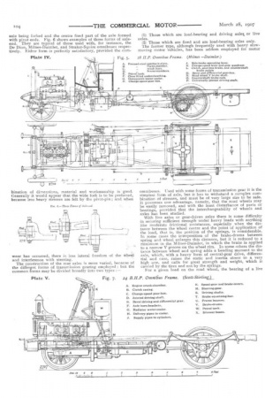
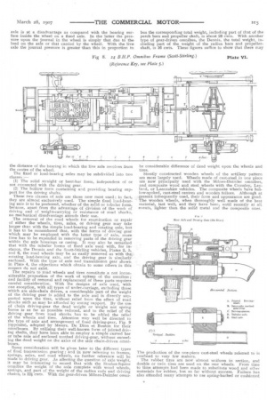
The removal of the road wheels for examination or repair of either the wheels, tires, axles, or driving gear may take longer than with the simple load-bearing and rotating axle, but it has to be remembered that, with the forms of driving gear which may he employed with the latter type of axle, more time has to be expended in removing parts of the driving gear within the axle housings or casing. It may also be remarked that with the tubular forms of fixed axle used with, for instance, the Dennis and the Scott-Stirling vehicles, Plates 2, 5, and 6, the road wheels may be as easily removed as with the rotating load-bearing axle, and the driving gear is similarly enclosed, With the type of axle and transmission gear shown in Plate 4, the objections which obtain to some others in this respect do not exist.
The repairs to road wheels and tires constitute a not inconsiderable proportion of the work of upkeep of the omnibus ; and facility of removal and replacement of these parts requires careful consideration. With the designs of axle used, with one exception, with all types of under-carriage, excluding those which are side-chain driven, a considerable part of the weight of the driving gear is added to the axle and is directly supported upon the tires, without relief from the effect of road shocks such as may be afforded by spring support. By the use of chain driving-gear the dead weight or weight not spring borne is as far as possible reduced, and to the relief of the driving gear from road shocks has to be added the relief of the wheels and tires. Attention may well be directed to the type of axle and arrangement of fixed driving-gear, Fig. 9 (opposite), adopted by Messrs. De Dion et Bouton for their omnibuses. By utilising their well-known form of jointed driving shafts, they have been able to employ a simple curved bar or tube axle and enclosed toothed driving-gear, without exceeding the dead weight on the axles of the side chain-driven omnibuses.
Some consideration will be given later to the different types of final transmission gearing ; and in now referring to frames, springs, axles, and road wheels, no further reference will be made to driving gear. As affecting the question of axle weight, it may be interesting to record that with the Straker-Squire omnibus the weight of the axle complete with wood wheels, springs, and part of the weight of the radius rods and driving chains, is 12i cwts. With the gear-driven Milne's-Daimler ornni
bus the corresponding total weight, including part of that of the perch bars and propeller shaft, is about 23 cwts. With another type of gear-driven omnibus, the Dennis, the total weight, including part of the weight of the radius bars and propeller. shaft, is 16 cwts. These figures suffice to show that there may be considerable difference of dead weight upon the wheels and tires.
Stoutly constructed wooden wheels of the artillery pattern are most largely used. Wheels made of cast-steel in one piece are now principally used with the Milnes.Daimler omnibus, and composite wood and steel wheels with the Crossley, Leyland, or Lancashire vehicles. The composite wheels have hollow-spoked, cast-steel centres and wooden felloes. Although at present infrequently used, their form and appearance are good. The wooden wheels, when thoroughly well made of the best material, last well, and they have been, until recently at all events, lighter than the solid metal and the composite ones, The production of the one-piece cast-steel wheels referred to is confined to very few makers.
The rubber tires are now almost uniform in section, and double or twin tires are used on the rear wheels. From time to time attempts had been made to substitute wood and other materials for rubber, but so far without success. Failure has also attended many attempts to use spring-backed or cushioned
wooden block tires, and the use of spring wheels has not passed the experimental stage.
Engines.—The petrol engines now used are all of the fourcylinder vertical type. A few of the two-cylinder horizontal engines are in use, but they must be considered obsolete in type, and their makers now show preference for the vertical type.
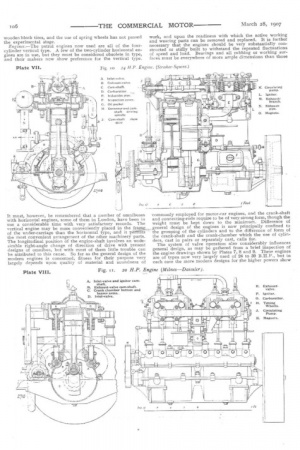
It must, however, be remembered that a number of omnibuses with horizontal engines, some of them in London, have been in use a considerable time with very satisfactory records. The vertical engine may be more conveniently placed in the fraras,„ of the under-carriage than the horizontal type, and it peftiits the most convenient arrangement of the other machinery parts. The longitudinal position of the engine-shaft involves an undesirable right-angle change of direction of drive with present designs of omnibus, but with most of them little trouble can he attributed to this cause. So far as the general design of the modern engines is concerned, fitness for their purpose very largely depends upon quality of material and soundness of work, and upon the readiness with which the active working and wearing parts can be removed and replaced. It is further necessary that the engines should be very substantially constructed or stiffly built to withstand the repeated fluctuations of speed and load. Bearings and all rubbing or working surfaces must be everywhere of more ample dimensions than those commonly employed for motor-car engines, and the crank-shaft and connecting-rods require to be of very strong form, though the weight must be kept down to the minimum. Difference of general design of the engines is now principally confined to the grouping of the cylinders and to the difference of form of the crank-shaft and the crank-chamber which the use of cylinders, cast in pairs or separately cast, calls for. The system of valve operation also considerably influences general design, as may be gathered from a brief inspection of the engine drawings shown by Plates 7, 8 and 9. These engines are of types now very, largely used of 24 to 30 B.H.P., but in each case the more modern designs for he higher powers show
some differences in detail. Drawings of the recent details were not obtainable, and are not here required, as the changes which have been found desirable will be referred to. Experience again shows that the successful running of the engines is largely determined by the type and arrangement of the important auxiliary parts used in connection with the carburetter and petrol supply, and with the water-cooling, lubrication and ignition systems. It is in the design and arrangement of these parts that the greatest difference of practice is to be observed, and to which the greatest interest attaches.
Carburetters.—As primarily affecting the power developed by the engine, some reference will first be made to the form of the carburetter commonly used. Fig. 13 shows the form employed with the large number of engines now in use with omnibuses of the Milnes-Daimler, and the Straker-Squire, or Bussing types. Air entering the jacket E at D, and warmed by contact with that part of the hot engine exhaust-pipe F within E, passes through the connectingpipe G to the carburetting chamber C. Unwarmed air may be admitted at H varying in quantity according to the set opening of the disc-shutter H. Petrol is supplied at A to the box B, and is there maintained at a constant height and about level with the top of the nipple C. Under the influence of suction from the engine, a jet or spray of petrol issues from the nipple, and mingling with the air passes by way of the throttle valve J and inlet-pipe M, to the inlet-valves, and so to the engine cylinders.
By restriction of the passage-way at the position of the top of the jet C, the rate of air-flow at that point is increased and greater suction or ejector effect occurs. The velocity of flow, when the throttle-valve j is open, is high, and at C may reach 6,500 feet per minute. At the high rate of flow of air through the carburetter a very fine air-petrol mist is produced, and at the low speeds of flow corresponding to low speeds of revolution of the engine, a sufficiently rich mixture is obtained to permit steady running of the engine. If difficulty is sometimes experienced in starting the engine, carburation of the air may be assisted by injecting a little petrol through the cock L at the top of the inlet pipe. The float chamber B is not shown in section, but it is of the commonly-used form with float and small pivoted levers to regulate the opening of the central needle-valve and the rate of flow of petrol past it, in order to maintain the constant level. Hinged bolts K are used to connect J and the intermediate piece to C. These parts may be quickly removed to expose the nipple C when carburetter troubles occur. This carburetter is of simple form, and equalisation of the quality of the mixture supplied to the engine at varying rates is not attempted.
With the carburetters* used with some recent designs of omrtibus an auxiliary air-supply is arranged, either controlled by the engine speed-governor or by variation of suction at different engine speeds. The position of the type of carburetter illustrated may be seen by reference to Plates 7 and 8. A device for averaging the pressure in induction-pipe, jet-chamber, and float-chamber, is also being used.
Among the most frequently recurring causes of stoppage of the engine is interruption of the petrol-supply, due to a variety of causes. When the supply to the carburetter is by gravity or difference of level of the tank and carburetter, failure of supply is generally due to either insufficient head or difference of level, or to choking of the pipe, and sometimes breakage of the pipe at the unions occurs. When, however, the supply to the carburetter depends upon maintenance of pressure in the petrol tank, it is also necessary to keep all joints in the pressure and feed-pipes and at the tank air-tight, and to ensure that the nonreturn valve at the engine end of the pressure pipe is in proper order. The possible causes of interruption of supply are thus somewhat more numerous when the pressure system, instead of the gravity system, is adopted. With the former system the supply tank may be carried at a distance from the engine at a lower level and in a convenient position for filling, generally under the frame at the rear of the vehicle. As a rule, however, the usual position of the tank with the gravity system, namely, under the driver's seat, is convenient enough for filling, and the connection to the carburetter is short, as may be seen by reference to Plate 1, and to Plate 5; the tank is shown at W.