


A DRIVER'S CAB IMPROVEMENT.
Page 40
If you've noticed an error in this article please click here to report it so we can fix it.
A Résumé of Recently Published Patents.
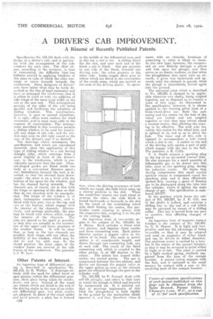
Specifieation No. 163,131 deals with the design of a driver's cab, and in particular with the arrangement of the side windows for such cabs, The chief object, according to the inventor, is that of overcoming the difficulty that has hitherto existed in applying windows of this class to cabs of which the sides converge or curve inwards towards the windscreen. Many designers of drivers' cabs have taken what may be fairly described as the line of least resistance and have so arranged the windscreen that it is either in itself or with the addition of side wings of the same total width as the cab at. the seat end. This arrangement permits of the sides of the cab being parallel and facilitates the adoption of sliding windows. This construction, however, is open to several objections. It is ugly, offers more surface for wind resistance, and in most eases adds to the expense of.construction. The arrangement described in this invention permits a sliding window to be used for practically any shape of cab side, and the window may even be slid right round to the rear of the driver's seat if en desired.
The drawings which accompany the specification, and which are reproduced herewith, show the application of this type of sliding window to a cab having straight sides, which converge from a point slightly in front of the driver's seat, to the windscreen, which is considerably narrower than the seat. Channel-shaped guides are fitted inside the body at a convenient distance apart; one, immediately beneath the roof, is 11)verted, so that the channel faces downwards ; the other is on a level with the bottom of the space for the window, and has the channel lacing upwards. The channels are, of course, cut in line with the hinge or-opening of ,the door so that they do not interfere with its inanipulation. The frame of the window is of plain rectangular construction, and is fitted with four pins, two at the top, and two at the bottom, which engage with the interior of the channels. Alternatively, and perhaps preferably, the pins may he fitted with rollers which, engage the interior of the channels. The pins are spaced as far apart as possible, so that they are actually at the extremities of the upper and lower members of the window frame. It will be • clear that, so long as the two channels are parallel, their shape will not affect the mobility of the window, which may he slid to and fro with ease. In the closed position the .front edges of the window frame are secured to the side frames of the windscreen. The patentee is .1. W. Law,
Other Patents of Interest,
An ingenious type of differential gear, fag is deseailied iii . specification No. 163,112, by -R. 'Walker. If dispenses en:. tirely With the need for either bevel or spur pinions within the differential gearcase, their place being taken by cranks, levers and pins. Instead of the usual sun wheels which are fitted to the end of the driving shafts in the case of an ordina ary differential gear, two plain cranks are adopted. In place of the usual spider arid _bevel pinions, a plain bar is formed
C56
in the Middle of the differential case, and in this bar a slot is cut. A sliding block fits the slot, and near each end of the
block a pin is fitted. One pin projects to one side of the block, towards one driving axle: the other projects to the other side. -Links couple these pins to others which are fitted in the extremities of the crank arms, which are carried on the ends of the driving skafts. In opera tion, when the driving resistance of both wheels are equal, the slide block takes up a central position. in the slot. When the conditions require one road wheel to overrun the other, the slide block is forced backwards or forwards in the slot by the crank of the overtaking wheel axle shaft. finding the centre, this particular crank rotating in unison with the respective link, coupling it to the pin in the sliding block., An ingenious forin of two-stroke engine is the subject of No. 163,055, by J. Mamma.. Each cylinder Is fitted with two pistons, and requires three cranks and three connecting rods. Each piston likewise carries a poppet valve in the centre of its head. The main or power piston is of considerable length, and drives through two connecting rods, one at each side. The crank of the third connecting rod, which is conpled to the other piston, is at 180 degrees to the
others. The piston last named Slides within the second piston. The gas is compressed between the two pistons, and driven out through the poppet valve in the upper piston. so .soon as the exhaust gases are releaied.through,the port in the cylinder wall.
No. 163,239, by P. Stumpf, deals with self-lift ploughs, and refers to that type in which the plough is lifted and lowered ,by -compressed air. It is pointed out that in previous implements of this kind the ploughshare is held rigidly in the g.olind by the mechanism which Operates it, and that, therefore. when it meets with an obstacle, breakage of something or other is like.ly to ensue. In this new type, however, the compressed air acts directly through a piston and link upon the plough, and Ihue serves as an elastic medium, so that when theploughshare does meet with an obstacle, it gives way backwards and upwards until the obstacle is passed, when the plough is immediately forced again into the ground.
The universal joint which is describedin No. 163,231 is claimed to be applicable wherever two shafts, being coupled. together, are so disposed as to require a joint of this type. As illustrated in the specification, however, it is shown applied to the steering pivot joint of a front-wheel-drive ear. Both the axle casing and the centre for the hub of the wheel are forked and are coupled together so that they may swivel about -a-vertical centre, thus allowing the steering to be effective. The stub axle lies within this centre for the wheel hub, and is splined at ita end so as to drive the hub. The inner end of this axle is tapered to accommodate a ball round ivhich a slot is cut. A socket on the end; of the driving axle carries a pair of pins which engage with the slot in the ball. The patentee is R. Collis.
F. A. -Smith mounts a sparking plug ' at the top of an air-cooled venturi tube. He also arranges for a small quantity of inflammable gas to he drawn into this tube, close to the sparking plug, during the induction stroke. Ire claims that during compression this small special ignition charge is compressed round the sparking plug and is thus effectively ignited first., causing a spurt of flaming gas to be discharged along the tube into the cylinder, where it ignites the main ehargeof gas. Thespecification is numbered 163,077.
In the gearbox which forms the sub: iect of No. 163,057, by J. E. Gill, one of the shafts is hollow, and contains a eliding key on the end of a rod which may be operated by means of a sliding collar. This key is moved from one gear to another, thus effecting changes of speed.
An ingenious form of magneto contact breaker is the enbiect of No. 145.405, by G. B. Gusset. It, is light and inexpensive, and has the advantage of being reversible so that it may he -adopted and used on magnetos of either hand, and can be driven in either direction Oneplatitinm screw is carried by a brae
i het n the centre of the contact breaker, so that it may be reversed to point either to right or to.left The other is carried by a light vertical spring, similarly supported from the base of the contact breaker. A second spring engages with the first, and is operated in the usual manner by contact with a cam on the revolving, part of the. contact breaker. !