


With Intent to Improve.
Page 20
If you've noticed an error in this article please click here to report it so we can fix it.
A Weekly Summary of Recent Patents, of Interest to the Maker and User of Commercial Motor Vehicles.
Selected and Abridged by H. S. Hall, A.M.I.A.E.
A Useful Type of Grease Cap.
What appeaas to be a useful method of retaining the cap on a grease cup and preventing, its loss on the road is described by F. Tyldesley, of 7, Cohn Street, Wigan, in specification 106,222.
A central spindle, firmly attached to the cap of the grease cup, which is otherwise Of normal design, has turned in_ it circumferential V shaped grooves, evenly and closely pitched along the whale of its length. The shank of the cup is bored to receive this spindle, and has also grooves cut along the side of its bore, which serve to allow a paSsage of grease past the spindle when the cap is being screwed down. A plate of spring steel is fitted into the base of the cup, and this plate ha,s projecting arms so designed that their ends bear in the grooves on the spindle. As the cap is screwed home, the ends of these spring arms follow the spindle for a while until depressed sufficiently to enable them to spring from one groove into the next.
It will be appreciated that a considerable force, or, alternatively, the-mechanical advantage due to the screwed thread, is necessary to overcome the resistance of these spring arms, and that they form a very effective safeguard against loss of the cap
Improved Chassis Design.
H. E. Back, Moss View, Rutland Street, Swinton; Lancashire, describes in specification No. 105,999' an improved articulated chassis. In this design of vehicle the load-carrying frame is independent of that to which are attached tho engine and main parts of the transmission. This load-carrying frame is attached through the medium of springs to the rear axle, which is of any customary type. Rigidly connected to the axle is a frame, the other end of which takes a bearing upon journals on a ' horizontal cross-member carried by the front part of the frame, this cross-member being so supported. that it can rotate about the longitudinal axis of this ' front chassis. The sa.ma cross-member is made, of double banjo forin, and its hollow centre surrounds the Universal joint which connects the Main portion of the trans Mission to the propeller shaft. , Upon the frame, which we have mentioned as being rigidly attached to the rear axle, is mounted an inverted semielliptical spring, to the apex of which is secured the transmission-carrying chassis.
It will be gathered that universal movement is possible as between the two main sections of this frame.
The principal claim covers a motor vehicle having an articulated chassis in which the tractor 'wheels are arranged on one part, and the motive power on the • ether part; co arranged that the parts of the chassis are free to rock independently about the longitudinal axis and ta permit a relative rotary movement about the transverse axis without ad' versely affecting the transmission gear.
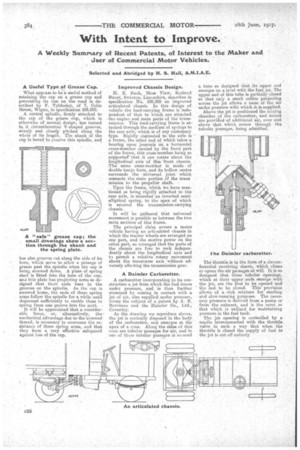
A Daimler Carburetter.
A carburetter incorporating in its construction a jet from which the fuel issues under pressure, and is then further atomized by coming in contact with a jetof air, also supplied under pressure, forms the subject of a patent by A. E. Berriman and the Daimler Co., Ltd., Coventry. An the drawing we repro-duce shows, the jet is centrally disposed in the body of the carburetter, and, emerges at the apex of a cone. Along the sides of this cone are tubular passages for air, and in one of thise tubular passages is secured a tube so designed that its upper end emerges on a level with the fuel jet. The upper end of this tube is partially closed BO that 'only a sanall orifibe projecting across the jet allows a issue of the air under pressure with•which it is supplied.
Above the jet is positioned the mixing chamber of the carburetter, and means are provided of additional air, over and above that which enters through the tubular passages, .being adibitted.
The throttle is in the form of a circumferential revolving sleeve, which closes or opens the air paasages at will. It is so designed that these tubular openings, which at their upper. .ends emerge with the jet., are the first to be opened and the last to be closed. This provision allows of a rich mixture for starting and slow-running purposes. The necessary pressure is derived from a pump or from the exhaust, and is the same as that which is utilized for maintaining pressure in the fuel tank.
The jet opening is controlled by a needle interconnected with the throttle valve in such a way that when the throttle is closed the supply of fuel to the jet is cut off entirely