


SELF-LEVELLING SUSPENSION
Page 72
If you've noticed an error in this article please click here to report it so we can fix it.
1-1. A CONSTANT-LEVEL suspension 1-1.
valve is shown in patent No. 865,952. It is said to. have a long life. (Engineering Research and Application, Ltd., London Road, Dunstable, Beds.) An air bellows is located between the axle assembly and the frame. Air pressure control is automatic through a spool valve which is responsive to changes in frame height following the application of load.
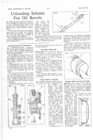
• The drawing shows one of several ways of constructing the valve unit. The rod (1) is not fixed to the body but is actuated by a lever pivoted on the body and connected to an unsprung part of the vehicle.
The rod moves the spool valve, opening a pressure port (2) to the bellows port (3), or alternatively the exhaust port (4), according to the direction of movement. A duct (5) applies the air pressure to the end of the valve, loading it against a spring (6).
Though the drawing shows no dash
pot, one may be fitted to the control rod if found desirable.
LONGER TYRE LIFE
pROGRESS in the design of tyres is disclosed in patent No. 867,541 which shows a built-in reinforcing band claimed to give increased tread life. (Dunlop Rubber Co., Ltd., 1 Albany Street, London, N.W.1.)
Thc drawing shows the additional band (1). Its thickness is exaggerated in the drawing, its actual size being 0.002 in. in the middle increasing to 0.004 in. at the sides. The material is a proprietary substance known as " Manes "; this has a Young's Modulus of up to 2,000,000 p.s.i. and a modulus of rigidity of up to 700,000 lb.
The thickened edge portions may be reinforced with cords of steel wire, nylon or Terylene.
HEAVY-DUTY CLUTCH
A CLUTCH designed to withstand con:r siderable heating is shown in patent
No. 866,034. . In general the layout follows disc brake practice. (Twin Disc Clutch Corp., 1328 Racine Street, Racine, Wisconsin, U.S.A.)
Referring to the drawing, the driving member is a. disc (1) and the driven unit a plate assembly (2). The duties of these two parts can, however, be reversed.
The plate assembly carries six pairs of tongs (3), one half of each pair being pivoted on a sliding sleeve at points (4) whilst the other halves are similarly pivoted on a movable plate 45). Release is provided by springs (6) ‘which tend to open thelongs.
Engagement is
• -BRAKE DRUM MANUFACTURE DRAKE drums made of' two different LI materials are shown in patent No. 866,880. The aim is to provide a durable rubbing surface combined with lightness and good heat conductivity. (KelseyHayes Co., 3600 Military Avenue, Detroit, Michigan, U.S.A.) numerous sawteeth on its _inner :edge. (3) so that when it is asseinbled in the shell, the teeth are forced 'into the soft alloy and form a multitude of keys..'
_The linet. is held diametrically by an interference fit and 'fitted by heating the shell and Cooling the liner.