


A Remedy for Valve-seat Distortion
Page 36
If you've noticed an error in this article please click here to report it so we can fix it.
A Re'surne of Patent Specifications That Have Recently Been Published
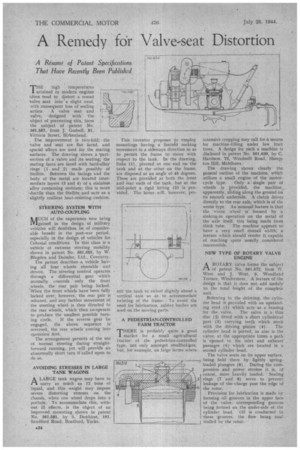
THE high temperatures attained in modern engines often tend to distort a round valve seat into 'a. slight oval, with consequent loss of sealing action. A valve seat and valve, designed with the object of preventing this, form the subject of patent No. 561,587, from J. Godsell, 81, Vitt-Oda Street, Birkenhead.
The improvement is two-fold; the valve and seat are flat faced, and special alloys are used for the mating surfaces. The drawing shows a Tartsection of a valve and its seating; the mating faces are faced with hard-alloy rings (1 and 2) made possibly of Stellite. Between the facings and the body of the metal are located intermediate layers (3 and 4) of a stainless alloy containing niobium; this is more • ductile than the Stellite and acts as a slightly resilient heat-resisting cushion.
STEERING SYSTEM WITH AUTO-COUPLING
MUCH of the experience now being gained in the design of military vehicles will doubtless be of considerable benefit in the post-war period, especially in the design of vehicles for Colonial conditions. In this class is a vehicle crl extreme steering mobility shown in patent No. 561.685, by W. 131agden and Daimler, Ltd., Coventry.
The patent describes a vehicle having all four wheels steerable and driven. The steering control operates through a differential gear which normally controls only the front wheels, the rear pair being locked. When the front wheels have been fully locked over, however, the rear pair is released, and any further movement of the steering wheel is then directed to the rear wheels, which then co-operate to produce the smallest possible turn ing circle. If the reverse gear be engaged, the above sequence is reversed, the rear wheels coming into operation first. The arrangement permits of the use of normal Steering during straightforward running, yet will provide an abnormally short turn if called upon to do so.
AVOIDING STRESSES IN LARGE TANK WAGONS
ALARGE tank wagon may have to carry as much as 12 tons of liquid, and this weight may impose severe distorting stresses on the chassis, when one wheel drops into a pothole. To accommodate this, without ill effects, is the object of an improved mounting shown in patent No. 5131,581, by S. DeWhirst, 191, Sandford Road, Bradford, Yorks.
This inventor proposes to employ mountings having a limited rocking movement in a sideways direction so as to permit the frame to move with respect to the tank. In the drawing, links (I), pivoted at one end on the tank and at the other on the frame, are disposed at an angle of 45 degrees. These are provided at both the front and rear ends of the tank, but at the mid-point a rigid fitting (2) is pro vided. The latter will, however, per mit the tank to swivel slightly about a vertical axis so as to accommodate twisting of the frame. To avoid the need for lubrication, rubber bushes are used on the moving parts.
A PEDESTRiAN-CONTROLLED FARM TRACTOR 'THERE is probab7y quite a good I market for a small agricultural tractor of the pedestrian-controlled type, not only amongst smallholders. but, for example', on large farms where intensive cropping may call for a means for machine-tilling under low fruit trees. A design for such a machine is disclosed in patent No. 561,630, by C. Harrison, 72, Windmill Road, Hampton Hill, Middlesex.
The drawing shows clearly the general outline of the machine, which utilizes a small engine of the motor cycle type. Only a single pair of wheels is provided, the machine,, apparently, sliding along the ground on its smooth underside. A clutch drives directly to the rear axle, which is of the worm type. An unusual feature is that the worm wheel is formed by a sinking-in operation on the metal of the axle itself, this being made from thick tube. The machine appears to have a very small overall width, a feature which should render it capable of reaching spots usually considered inaccessible, NEW TYPE OF ROTARY VALVE • ENGINE
PAA ROTARY valve forms the subject of patent No. 561,572, from W. West and J. West, s, Woodland Terrace, Windermere. A feature of the design is that it does not add unduly to the total height of the complete unit.
Referring to the drawing, the cylinder head is provided with an upstanding stud (1) which acts as a bearing for the valve. The valve is a thin disc (2) fitted with a short cylindrical part (3) carrying teeth which mesh with the driving pinion (4), The cylinder head is ported, as also is the valve; at the appropriate times a path is opened to the inlet and exhaust passages (5). which are located in a second cylinder head.
The valve seats on its upper surface, tieing held there by lightly springloaded plungers (6). During the compression and power strokes it. is, of course, more heavily loaded. Sealing .5 rings (7 and 8) serve • to prevent leakage of the charge past the edge of the rotor.
Provision for lubrication is made by forming oil grooves in the upper face of the valve, corresponding grooves being formed on the under-side of the cylinder head. Oil is conducted to these grooves, the flow being cou!
trolled by the rotor. •