


A Flywheel-assisted Transmission
Page 54
If you've noticed an error in this article please click here to report it so we can fix it.
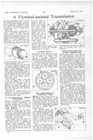
ATRANSMISSION system in which a fast-running flywheel is used to absorb energy when braking and return it for acceleration is shown in patent No. 720,272. The patentee is Gyreacta Transmissions, Ltd., 1 Tilney Street, London, W.I.
The drawing shows a vehicle gear in which 1 is the input shaft and 2 the output member. A primary reduction is given by an epicyclic gear (3) to the runner (4) of a hydraulic coupling. The impeller (5) of the coupling is connected to a crown-Wheel (6) driving a bevel pinion (7). This is in line with the energy-storing flywheel (8) and can be clutched thereto, when required, by an electro-magnetic unit (9).
The full description of the action of the various magnetic clutches would require several drawings, hut the overall action is easily understood. The flywheel, which runs at 20,000 r.p.m., is not intended to stop during normal use, so if the vehicle has been idle for some days it has to be run up to its working speed, either by the vehicle engine or by external means.
Once running, it can be used first to start the engine, then to provide acceleration and finally as a brake, in which case it is speeded up. The flywheel is brought into action by admitting fluid to the hydraulic coupling and energizing the particular clutch required.
Draining the coupling throws the flywheel out of action. Governors are provided to limit the flywheel speed to its maximum safe value.
AN ALL-MECHANICAL TORQUE CONVERTER
SAIDto be suitable for road vehicles and industrial applications, an infinitely variable gear is shown in patent No. 720,089 (J. and R. Wooler; Willow Bungalow, West End Road, Ruislip, Middlesex).
The gear works on the known principle of transforming the rotary motion into reciprocating motion, which is then passed through a variable lever and finally Converted back to rotary motion by a one-way clutch.
The drawing shows the actual construction of the heart of the gear. An input shaft carries a %ariable-throw eccentric which successively reciprocates four arms (1) about their centres (2). The eccentric can be set to rock the lever arms through any angle from zero up to 70°.
Each arm is part of a one-way clutch a28 housed inside a pinion (3) and when rocked it turns the pinion on its working stroke and returns idly. There is overlap between the working strokes of the four pinions and this is said to give a uniform turning moment to the central sun gear (4). which forms the output member.
The patent gives • drawings and descrip tions of the whole gearbox, which gives in addition to the variable ratio, a reverse and a straightthrough lock for top gear.
A SAFETY DEVICE
ASAFETY device which comes into action when a tyre bursts is dealt with in patent No. 720,671 (W. Vollstedt, 7 Osdorfer Landstrasse, Harnburg-Grossflottbek, Germany).
It consists of a small wheel attached to a convenient point on the axle so as just to clear the ground. Should the tyre deflate, the wheel would support the vehicle until it was brought safely to a standstill.
THE LATEST DESIGN IN PNEUMATIC TYRES WHEN a wheel is steered there is a VT twisting action imparted to that part of the tyre tread that is in contact with the ground, and subjects the tyre to high shear stresses. A tyre that will better withstand this treatment is shown in patent No. 720,150 (Dunlop Rubber Co., Ltd., I Albany Street, London, N.W. I). The drawing shows the various layers of the proposed lyre. On the foundation sheet is a pair of rubberized textile cords (1) which are wrapped round the beads in the usual manner. A sheet of rubber (2) is then overlaid, and on top of this are two layers of steel cord (3).
These are rubberized and are
separated by a layer of nylon (4). The conventional tread is then applied to the outer layer of rubberized steel cords. As
an alternative to the layer of nylon, a sheet of Terylene fabric can be employed.
MAINTAINING CONSTANT ENGINE TEMPERATURE rr HE cooling system of an engine is
usually designed to deal with the heat output generated at full load on a. hot day; this means that at other times 'and at partial load the engine is often over-cooled, with a consequent loss of efficiency. A scheme for adjusting the rate a cooling to the load obtaining at any given time forms the subject of patent No. 720,330 (Morris Motors, Ltd., Cowley, Oxford).
In this scheme, the radiator is divided into two separate units, a primary unit (1) of small capacity and a larger section (2). Used together, they can deal with the maximum heat output. The two units have a common bottom tank and outlet, but at the top each has its own inlet; they do, however, join at a point in the main riser.
The inlet to the larger section contains a,. butterfly valve (3), which is coupled by rodwork to the throttle pedal. In operation, at low throttle openings, the valve remains shut and the 'small radiator alone is in operation. When the throttle is opened, the larger section is brought into use by the opening of the butterfly valve. A snap action is preferred for the valve; this is given by a spring and a lost-motion coupling (4). The usual thermostatic valve (5) is fitted in the riser to the small section, so as to give rapid heating•from cold.