


Improvements in Road Sweeper Design
Page 28
If you've noticed an error in this article please click here to report it so we can fix it.
pATENT No. 608,402 discloses the latest proposals in the design of road-sweeping vehicles. The patentees are Lewin Road Sweepers, Ltd., A. Dear and F. Heathcote, all of Victoria Works, Hill Top, West Bromwich.
The vehicle is a three-wheeler, having a pair of driving wheels at the front and a single rear wheel (I) through which steering is effected. The engine is located at point 2, whilst the rest of the bodywork is devoted to a water tank and a receptacle for the sweepings.
The rotary brush (3).lifts the sweepings. into a casing, whence they are fed on to a rising conveyor chain (4). This takes, the rubbish to the top and
discharges it into the body. The conveyor as a whole, and the rotary brush, are pivoted about the driving. railer (5) so as to allow for variation of road height. The adjustment for this is performed by a pair of cables (6) which can be hauled in or out by a handwheel (7) in the driver's cab.
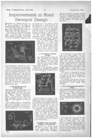
A MILES-PER-GALLON INDICATOR
AN instrument for indicating, at any moment, the miles-per-gallon of a running vehicle is shown in patent No. 608,305, by Jeffreys and Edmunds, Ltd., Station Parade, Whyteleafe, Surrey. The driver sees a short glass tube containing coloured liquid, the height of which indicates the consumption.
The drawing shows a conventional type of petrol pump (1), to which the new device is attached. Shown also is the float-chamber (2) of the carburetter, with its needle valve. As is well known, the diaphragm of the pump is pulled downwards by a rocker operated by the camshaft (3), but rises only under the action of a spring. If little petrol is being consumed by the carburetter, then the stroke of the diaphragm is reduced; conversely, a high consumption means a longer diaphragm stroke.
In the present scheme, use is ingeniously made of this fact to act as a measure of consumption. Worked by the pump diaphragm is a pair of levers (4), which reciprocate a second diaphragm (5); this acts as a pump to the coloured fluid; which rises in tube 6. Greater stroke means greater height of fluid, owing to the use of a leaky non-return valve in the piping.
A UNIVERSAL ENGINE STAND
EAA SWIVELLING stand for facilitating the overhaul of engines, is shown in patent No. 607,803, by Sykes and Robinson, Ltd., and C: Sykes,
both of . Royal Park Works, Queens Road, Leeds, 6.
Referring to " the drawing, a stout A-frame carries bearings Ifor trunnions" (1) which support the swingitfe:POrtion.
The last consists of a pair of sidemembers (2) which are slotted for their whole length, so as to permit adjustment of the position of the engine bearers (3). These are made Z-shaped to carry the engine low enough for its centre. of gravity to approach the trio-anion axis,, thus achieving a good balance in ail positions. The cross-rnenibers (4) are also slotted to provide adjustment for width, the trunnions being excessively long for the same purpose. A disc (5), drilled with numerous holes, enables a pin to be inserted to lock the frame at any desired angle.
GEARBOX FOR USE WITH TORQUE CONVERTERS
PATENT No, 609,389 comes from A. Gatiss, and Brockhouse Engineering (Southport), Ltd., Rufford Road, Southport,
and gives details of a gearbox intended for use in conjunction with a torque converter. Actually, the patent is concerned with only a detail, but in view of the interest the whole unit is described.
In the drawing, I is the input shaft and 2 the output member. The box gives only two speeds and a reverse, the torque converter, presumably, providing the rest of the speed range. The input shaft carries a fixed. pinion driving a layshaft gear -(3) fromwhich another pinion (4) drives a gear (6) freely jowl-railed on the output shaft. A dog-clutch, shown generally at 5 can provide either a direct drive or a double-reduction through the layshaft gearing.
The reverse is obtained by the use of an idler (7) which actually meshes with gear 8 and can be engaged by a sliding dog (9) .which at the same time frees gear 4.
The subject of the patent is the synchronizing methods used on the central dog-clutch * to avoid shocks when changing.
A MULTI-SEGMENTED PISTON RING
AN unorthodox scheme for sealing a piston is shown in patent No. 609,256, by W. Hunt and C. Lever, 200, BrookIands Road, Brooklands, Cheshire. 'These inventors propose to form a piston-ring from numerous interlocking segments, each having its own spring.
In the drawing, 1 and 2 are the segments, which are assembled as indicated in broken lines. The other drawing (3) shows how the expansive force is supplied by helical springs, one to each piece. The chief advantage of the ring is that it more easily adapts itself to local irregularities in the cylinder than would a one-piece ring of the conventional type.