


MAN
Page 58
Page 59
Page 60
If you've noticed an error in this article please click here to report it so we can fix it.
NNOVATIONS ffiINT 4x 4
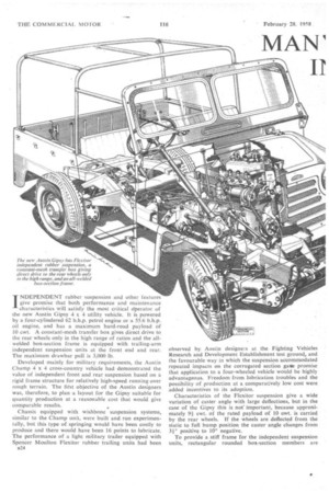
INDEPENDENT rubber suspension and other features give promise that both performance and maintenance characteristics will satisfy the most critical crperator of the new Austin Gipsy 4 x 4 utility vehicle. It is powered by a four-cylindered 62 b.h.p. petrol engine or a 55.6 b.h.p. oil engine, and has a maximum hard-road payload of 10 cwt. A constant-mesh transfer box gives direct drive to
the rear wheels only in the high range of ratios and the allwelded box-section frame is equipped with trailing-arm independent suspension units at the front end and rear. The maximum drawbar pull is 3,000 lb.
Developed mainly for military requirements, the Austin Champ 4 x 4 cross-country vehicle had demonstrated the value of independent front and rear suspension based on a rigid frame structure for relatively high-speed running over rough terrain. The hist objective of the Austin designers was, therefore, to plan a layout for the Gipsy suitable for quantity production at a reasonable cost that would give comparable results. ..
Chassis equipped with wishbone suspension systems, similar to the Champ unit, were built and run experimentally, but this type of. springing would have been costly to produce and there would have been 16 points to lubricate. The performance of a light military trailer equipped with Spencer Moulton Flexitor rubber trailing units had been B24 observed by Austin designers at the Fighting Vehicles Research and Development Establishment test ground, and the favourable way in which the suspension accommodated repeated impacts on the corrugated section gale promise that application to a four-wheeled vehicle would be highly advantageous. Freedom from lubrication troubles and the possibility of production at a comparatively low cost were added incentives to its adoption.
Characteristics of the Flexitor suspension give a wide variation of caster angle with large deflections, but in the case of the Gipsy this is not' important, because approximately 9+ cwt. of the rated payload of 10 cwt. is carried, by the rear wheels. If the wheels are deflected from the static to full bump position the caster angle changes from 31° positive to 100 negative.
To provide a stiff frame for the independent suspension units, rectangular rounded box-section members are employed, a notable feature of which is complete sealing against the ingress of moisture. This will obviate internal corrosion in those overseas districts where the corrosive action of mud may be severe.
The type of section used eliminates local stress concentration at points in the frame members remote from the neutral axis, which is of special importance because high loads are locally imposed on the members at the ends of the frame by wheel movements.
Radiused corners reduce torsion stressing and provide even stress distribution throughout the length of the frame. They also enable cross-members of similar form (the radius is 1 in.) to be fitted with a high degree of accuracy.
All-welded construction is employed and the two sections of the members are joined together in an automatic welding machine at the sides, rather than at the top, so that the lines of maximum stress extend along an unbroken metal surface. An exception to this rule is the rear cross-member, which is welded at the top and bottom and has a transverse reinforcing plate. Sections of this plate extend through slots in the members and are welded in position, thus providing additional resistance to bending to accommodate high towing-hook loads.
The main frame members, which are of 14 s.w.g. material, taper at their outer ends and are cranked over the axles. At the centre the box section measures 6 in. by 3 in. and is reduced to 4 in. by 3 in. at the front and rear.
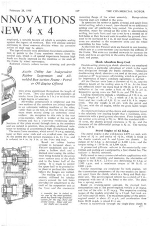
Based on rubber bushes stressed in torsional shear, a Flexitor suspension unit comprises a hollow shaft and a divided outer casing, the rubber bush being bonded to the entire outer surface area of the shaft and to the lower half of the casing. It is made to permit the upper half to be pressed into place to pre-load the rubber before the flanges are welded. The trailing arm is of box section, stiffened by tubular spacers around the bolt holes provided for attachment to the shaft of the suspension unit at the front and the concentric mounting flange of the wheel assembly. Bump-rubber wearing pads are welded to the ants.
In operation the rubber is lightly stressed, and apart from initial settling, which is small, there should be no additional settling over art indefinitely long period. No provision is, therefore, made for setting-up the arms to accommodate settling, but both front and rear arms have a second set of bolt holes at their forward ends to enable the ground clearance to be increased by 1 in. to suit local conditions. The arms are attached to the suspension units and the wheel assemblies by four bolts.
At the front two Flexitor units are located in one housing, which acts as a cross-member and increases the stiffness of the frame. The arms are cranked outwards to increase the track and have an aperture in the centre through which the track rod passes.
Shock Absorbers Keep Cool
Double-acting piston-type shock absorbers are employed at the front, a particular advantage of which is the rapid heat • dissipation through the frame members. Telescopic double-acting shock absorbers are used at the rear, and are inclined at 45° to promote roll stability, which is of particular importance if heavy auxiliary equipment is carried.
All the Flexitor units have a diameter of 41 in., and the effective length of the trailing arms is 13 in. At the front the deflection under the static load of 700 lb. is 2.9 in. and deflection at the rear under a load of 438 lb. is 2.6 in. Respective spring rates are 240 lb.-in. and 270 lb.-in.
Leading dimensions include a wheelbase of 7 ft. 6 in., an overall length of 11 ft. 7 in., a width of 5 ft. 64 in. and front and rear tracks of 4 ft. 64 in. and 4 ft. 4 in. respectively. The dry weight is 24 cwt. with the petrol and 251cwt. with the oil engine, whilst the gross laden weight is 2 tons.
An important feature of the chassis and suspension layout is the relatively low loading height that it facilitates, commensurate with a good ground clearance. Floor height with the normal arm setting is 261 in. With the standard 6.0016 tyres, the chassis ground clearance is 91 in., and the clearance of the differential casings is 84 in. The turning circle is 35 ft.
Petrol Engine of 62 b.h.p.
The petrol engine is the well-known 2,199 c.c. unit, with a bore of 34 in. and stroke of 44 in., which is fitted in the Austin taxicab and 1and 14-ton ton chassis. Its output of 62 b.h.p. is developed at 4,100 r.p.m., and the torque rating is 110 lb.-ft. at 1,500 r.p.m.
A pressurized gill-tube radiator is thermostatically controlled, and cooling air is supplied by a four-bladed fan. The radiator is flexibly mounted.
Fully tested in many commercial-vehicle applications with regard to both reliability and economy, the alternative oil engine is the B.M.C. 2.2-litre unit developing 55 b.h.p. at 3,500 r.p.m. and a maximum torque of 89 lb.-ft. at 2,800 r.p.m.
Similar mountings are employed for both engines. All the transmission components of the two models are identical, apart from the clutch, which is a Borg and Beck dryplate unit. The petrol-engined vehicle has a clutch of 9 in., compared with one of 10 in. fitted to the oiler. The plate has a sprung centre.
Based on cruising-speed averages, the claimed fuelconsumption rate of the petrol-engined vehicle is 25 m.p.g. and that of the oiler is 32 m.p.g. The respective cruising ranges of the models provided by a 13-g1l. fuel tank aie 325 miles and 420 miles. The maximum speed of the petrolengined model is about 63 m.p.h. and acceleration time from 10-30 m.p.h. is about 11.4 sec.
Power is transmitted through the single-plate clutch to s25
a four-speed gearbox with baulk-ring synchronization for top, third and second ratios, and thence to a transfer box bolted to the rear of the gearbox. The input and output shafts are co-axial, and in the top gear of the high range the input shaft of the transfer box is coupled to the tailshaft to give direct drive to the rear wheels without engaging front-wheel drive.
It is impossible, however, to employ the low range of gears without engaging both front and rear-wheel drives, so that the maximum torque in the low range is always divided between the two drives. This has the advantage that a standard private-car type of differential can be employed giving a high overload rating.
Gear Ratios In third gear the gearbox gives a reduction of 1.37 to 1, and the second ratio is 2.35 to 1. A bottom gear of 4.05 to I is employed and the ratio of the hypoid-bevel final drive is 5.125 to 1. When the drive is transmitted through the transfer box, reduction is multiplied by 2.02, which gives an overall top-gear ratio of 10.35 to 1 and a first-gear ratio of 41.93 to 1. In the high range the first gear ratio is 20.756 to 1 and reverse has a ratio of 26.45 to 1. The low range reverse ratio is 53.4 to 1.
When the transfer box is in operation, the drive is transmitted from a helical gear keyed to the input shaft to a layshaft, the second gear of which meshes with the wheel on the tailshaft and with one on the front-drive output shaft. When four-wheel drive is engaged, this is locked to its shaft and the upper gear is coupled to the tailshaft driving the rear wheels. The drive shafts between the gearbox unit, the differentials and the wheels are equipped with HardySpicer joints.
Girling hydraulic brakes are fitted to all wheels, their area being 133 sq. in. Drums measure 10 in. by 1-1 in., and the braking ratio is 65/35. Alternative tyres include 6.50-16, 7.00-16, 7.50-16 and 8.90-15 covers, the 8.90-15 being mounted on 6.00-15 wheels.
A high-efficiency cam steering box is used and all the joints are bushed with nylon, for which no lubrication is required. The only component requiring lubrication, apart from the box, is a relay unit and this has a large reservoir which enables it to operate almost indefinitely without replenishment.
Ali-welded Body
The all-steel welded body is built as a unit, which is mounted on a total of six rubber washers and is attached to brackets. The sides are formed from a single sheet to a shape that provides a robust capping rail and box-section reinforcements.
Box-section members are also, employed in the construction of the main door pillars and a mating cross-member under the cab bulkhead, to which a similar longitudinal member is welded, which extends to the rear of the threepassenger bench seat. This has three shaped squabs covered in p.v.c.-coated leathercloth.
Inside, the body is 3 ft. 91 in. long, 4 ft. 10iin, wide overall, 3 ft. 1 in. wide between wheel-arches and 1 ft. 5 in. high, giving a capacity of rather more than 23 Cu. ft. The two doors are easily detachable after opening fully. This applies also to the rear-hinged bonnet, which has a clip to hold the two-panel windscreen when it is folded open.
.Thebonnet is held closed by lift-up safety catches and the
door, catchesare controlled by internal cables. Parcel shelves are located to the left and right of a central instruJnent panel, a hinged section of which gives access to the electrical wiring.
In the rear compartment, the wheel-arches provide space for built-in tool boxes, and seats for six extra passengers can a26 be fitted as an optional extra. The spare wheel is mounted behind the main seats.
An electrical windscreen wiper is standard equipment on the driver's side and provision is made for a second wiper. The windscreen is of toughened plate. All-weather equipment includes detachable door side screens, a p.v.c.-covered tilt and hoopsticks, the tilt being attached to the windscreen by press studs and roped to the body side panels.
The electrical system is based on a 12v. 51-amp.-hr. battery, and the equipment includes separate bead and side lamps, twin stop tail lights and flashing direction indicators.
Available as an optional extra, a power take-off can be mounted on top of the transfer box and equipped with an extension to the rear of the vehicle to operate a drum pulley, the extension being similar to the one that was fitted to the Champ. Alternatively, a V-pulley drive can be fitted for the operation of attachments mounted in the vehicle.
• Other extras include a capstan and a spool winch, which are driven from the front of the engine through a dog clutch, and a 500 g.p.m. fire pump driven through a friction clutch, which is mounted at the front. A towing hook is fitted as standard.
A high precedent has been established for this type of vehicle, and the Austin designers obviously had no, illusions with regard to the rought treatment that the Gipsy will have in the hand of many drivers. Extended tests on the Motor Industry Research Association's proving ground were completed before the design of the production model was finally approved. The cross-country payload rating is 5 to 7 cwt.
Road Test Impressions
The suspension is the all-important feature of the Gipsy [writes John F. Moon, who has taken one of the first production models over a full-length road and crosscountry tests carrying the full payload of 10 cwt.]. The Austin was driven over the F.V.R.D.E. pave and raised-sett courses at over 40 mlp.h. in relative comfort and with complete control being maintained.
Engine power is sufficient to take the chassis with 10-cwt. 'load up a 1-in-2 gradient. On the road the steering at first seems somewhat vague, but after a few hundred miles it is possible to become accustomed to this effect, which is a combination of understeer and oversteer. In terms ofcomfort the vehicle is rather austere, but it has obviously been designed as a purely working vehicle and makes no pretence at providing private-car facilities.
The synchromesh of the four-speed main gearbox is effective, and although it causes the change to be a little stiff, fast Changes through the gears can be made when in a hurry. Being a long-stroke unit, the petrol engine which powered the vehicle tested gave a good top-gear performance and was reasonably free from vibration throughout its whole speed range. The wide alligator-type bonnet afforded good engine accessibility.
Test figures obtained with a 10-cwt. payload show the time taken to reach 50 m.p.h. from a standstill to be 23.5 seconds, whilst the time in direct drive between 10 m.p.h. and 50 m.p.h. was 32 seconds. Driven at high speeds a fuel-consumption rate of 16.5 m.p.g. at 38.5 m.p.h. average speed was obtained, whilst driving more carefully a figure of 20.9 m.p.g. was returned. Unladen, a fuel figure of 18.1 m.p.g. was yielded at an average speed of 37.5 m.p.h. and 22.1 m.p.g. when driving without exceeding 35 m.p.h.
The average braking distance from 30 m.p.h. was 44 ft., but the hand brake was disappointing, producing only 14 per cent. efficiency when applied from 20 m.p.h. The turning circles are somewhat large-41.5 ft. on left lock and 40 ft. on right lock. All these tests were conducted with the vehicle running at a gross weight of 2 tons 01 cwt. The petrol-engined Gipsy sells for £650 and the oil-engined version costs £105 more. The power take-off costs £47 10s.