


Flexible Axles.
Page 74
If you've noticed an error in this article please click here to report it so we can fix it.
HITHERTO axles have been of a
rigid nature and have relied on the springs which separate them from the frame for flexibility. The specification cf William Meurice, of Brussels, No. 284,181, however, describes an axle in -which springs are embodied between the part usually occupied by springs and the steering head.
The ends of the axle and the steering head are spread out into wide flanges suitable for supporting a number of thin leaf springs, which are separated by distance pieces and secured by long bolts to the flange. All the springs act simultaneously, but if any appreciable amountof deflection be expected from the short leaves, held as they are, we may expect their life to be only a short one.
Coupling Suitable for Petrol or Oil Pipes.
THE coupling described in the patent
specification No, 282,210, of A. La Rue Parker, of Cleveland, U.S,A., appears to be very suitable for the ripes which convey petrol or oil to the various parts of motor vehicles. The specification not only describes the form of coupling, but it also describe.3 a simple tool for flaring out the end of the pipe. The tool is used to flare the end of the pipe after the union nut has been slipped on the pipe, the ball-shaped portion forming a
, n48 slight swell in the pipe, which makes it a good fit in the union nut. In forming the two cones, between which the flared end of the pipe is nipped, allowance must be made for the thinning of the metal of the pipe. Joints of this kind can be made fluid-tight without packing of any kind, and, as no brazing or soldering is entailed, they should find favour with manufac• turers of commercial vehicles, where the break age of petrol pipes is still a
fairly common oCcurre11e.3. if we can judge from the number of letters we receive from drivers, telling us how they managed to make temporary repairs of such pipes on the road. Should a pipe, coupled in this way, break, a driver would have but little difficulty in flaring the end out with some tool he can find among his kit. We wonder that some arrangement of the kind has not long ago superseded the costly and bad method of brazing a cone to the end of a nine.
Like many American "inventions," there appears to be practically no novelty in the design, as a pipe coupling device embodying the same principle has, for years, been manufactured by James H. Lamont and Co., Ltd., of Edinburgh,. and by William Barton and Sons, of the same city.
A New Elastic Joint.
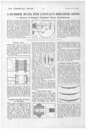
THE principle of the rubber bush
which depends upon the deformation of the compressed rubber to permit a slight angular movement of a member on a pin is now well known. The specification of the Compagnie d'Applications Mechaniques, of Ivry-Port,. France, No. 274,044, shows what it
describes as a removable elastic joint, in which a rubber bush is employed in connection with grooves or rings in the inner or outer member as shown in the illustration at the foot of the centre column.
No mention is made of how this bush is introduced into the space between the inner and outer member. The usual method by which such bushes are introduced is by compressing and elongating the bush so that its thickness is reduced, but in this case fibrous materialis mentioned as being introduced into the bush, which would prevent elongation and increase the difficulty.
A Curious Spring Invention.
AN argument with which we can
hardly agree is put forward by Paul A. Carteret, of Neailly, France, the inventor of the spring described in specification No. 279,889, in which he claims that the reaction of a spring can be considerably reduced by forming the various leaves from one long continuousstrip of metal as shown in the upper view. As springs are usually constructed, the ends of the leaves are more or less free to 'slide, and the centre is held so securely by the bolts which secure it to the axle that sliding at this part is entirely prevented. In the present case, however, only the bottom leaf is secured to the axle, all other leaves being allowed to slide. It is true that this may have the effect of damping out reactionary movements, but knowing the difficulty that is found of securely anchoring a spring to its axle with the present methods, we can foresee even greater difficulties when only the bottom, and shortest, leaf is anchored. The centre and lower views show other means ef carrying out the same idea.