


PROGRESS IN ENGINE DESIGN.
Page 67
Page 68
Page 69
If you've noticed an error in this article please click here to report it so we can fix it.
A Continuation of an Article Concerning Recent Advances Made in the Power Unit for the Commercial Vehicle. We Now Deal with Certain Features in Particular Engines.
I N the article which occupied our centre pages last week
we dealt at some length with the recent progress made in the oomniercial-vehicle engine, but, with a few exceptions, our remarks were of a general nature,, and we shall now continue the article by partioalarizing and drawing attention to certain new and interesting features evhich are embodied in the various designs. The space at our disposal does not permit our dealing with every engine ' on the market, add we have, therefore, selected a few makes which will serve to exemplify the various points raised, We axe not dealing with them in any particular order, but just as they come to hand.
One of the most recently produced series of chassis is the Commer, with the A-type engine, of which there are two eizes, these being identical except for thecylinder dimensions. The block is a one-piece casting with detachable heads in pairs, the arrangement giving the superior rigidity of the monobloc cylinder casting with the convenience of handling resulting from the employment of separate heads.
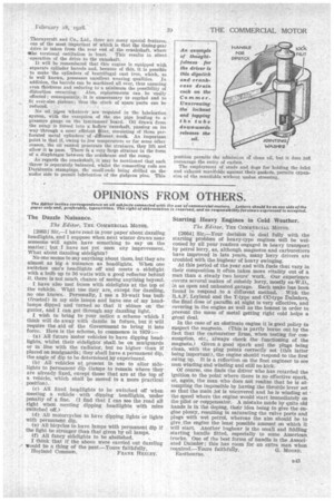
Although the design of the combustion chamber is such as to give a high degree of turbulence, it is interesting to note that a high power output has been secured with the comparatively low compression ratio of 4.5 to 1. With four cylinders of 110 ram, bore and 140 ram. stroke and an R.A.C. rating of . 30 h.p., 40 b.h.p. is developed at 1,000 ft. per minute piston speed, eorresponding to approximately 919 r.p.m, whilst 80 b.h.p. is developed at 3,000 r.p.m.
Aluminium pistons, each with two B.D.S.A. narrow-type rings and a special scraper ring, are provided. There are.22 On. diameter holes to permit the return of oil to the interior of the piston. The gudgeon pins are free, aluminium buttons preventing scoring of the cylinder walls. In the crankcase the sides are carried to some 4 ins. below the centre line of the crankshaft.
Valves made of Silchrome steel and with a special form of cone-fixing device for the spring cups are employed. Details of the cotter device were illustrated last week.
To give good distribution of the mixture, the type of manifold adopted has buffer or resurge ends with a separate lead to each inlet-valve port. Draining of the sump is carried out by loosening the nut which serves to hold the tube carrying the graduated dipstick. By tapping the tube downwards, slots cut in the lower portion are exposed. The method avoids the necessity of the driver crawling under the vehicle to reach a tap in the sump, as so often has to be done.
A novel method is employed for ventilating the crankcase. Cored holes in the upper face of tho crankcase register with a cored passage in the cylinder block. This passage
is carried upwards and across to the off side of the block, to which is attached an elbow pipe directing -the fumes to the ground. An impeller driven by the fan spindle assists In circulating the water, but, in the event of failure, circle. laden by thrino-siphonic action will continue. In view of the trouble whichhas been experienced with the corrosion of impeller spindles, it is of interest to note that, in this ease, the impeller is made of stainless steel.
Another feature is the adjustable pulley for the fan belt.
A further point is that the flanges of the bearings for the magneto and dynamo drives are each provided with 12 holes, of which three only are used by the fixing studs in the crankcase. The bearings are .006 in. eccentric; thus adjustment for meshing of the gears is permitted both in the original assembly and when reassembling after overhaul by changing to fresh sets of three holes.
No felt washers are employed, use being made only of reverse threads and oil throwers.
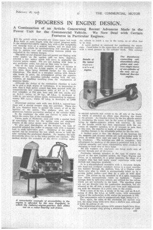
Particular interest attaches to the type of engine employed on the new Leyland models, the Tiger. Tigress and Titan, as it embodies, in a great measure, the ideas of a designer who has had many years' experience with both British and American products.
It is a-six-cylindered moriobloc with a one-piece detachable head and overhead camshaft driven in a most unorthodox manner through the medium, first, of a Duplex roller chain—any play in which is automatically taken up by a sprung jockey pulley—and then by a pair of wide skew gears. The pinion on the camshaft is of a split, expanding type which automatically takes up backlash. Duplex springs, held by split-cone cotters, are utilized for the valves, which are set vertically in the head. The sparking plugs are not set directly into the combustion chambers, but are situated at the off side, a small port from each communicating with the chamber at a point close to the centre.
With a bore of 4i ins., a stroke of 5i ins., and an R.A.C. rating of 38.4, the b.h.p. at 2,000 r.p.m., with economical setting of the carburetter, is 90, whilst the maximum is 105.
The compression ratio is comparatively high, being 5 to 1. Here, again, the sides of the crankcase are carried very low, the sump being little more than a shallow pan, although it holds 31 gallons of oil. The aluminium-alloy pistons with concave heads have three rings and a scraper ring, giving a minimum mileage of 1,000 B41 per gallon of oil. An unusual feature is that the white metal is cast direct into the alloy-steel rods ; also seven bearings, 21 ins. in diameter and giving a total area of 75.6 Sq. ins., are provided for the crankshaft.
Resurge ends are used in the induction manifold and one cflrburetter is found to give effective carburation.
Novel features are also to be found in the lubrication syStem. For instance, the oil pump is a dual type employ lag two separate sets of pinions, the larger delivering to the main bearings
and big-ends and the smaller to the timing gear and overhead camshaft. A percentage of the oil thrown from one of the big-ends is carried under a felt filter, the whole of the .oil passing through this filter three or four times a day, with the result that the oil remains green after thousands of miles of use, showing that it is practically free from particles of carbon. By interconnecting the oiling system and the throttle the pressure of 5 lb. to 10 lb. at small throttle openings is increased to 75 lb. to 100 lb. at full throttle.
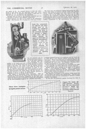
The engine is remarkably clean externally. This is assisted by driving the fan direct from the timing gear and concentrating all impOrtant auxiliaries at the near side; whilst the maintenance of cleanliness during use is facilitated by the stove-enamelled finish of the cylinders and heads. The latest Guy six-cylindered engines incorporate the wellknown Guy design of inclined cylinder beads and inclined valves. Certain advantages have been found in this construction, one of the chief being that there are no side pockets in the combustion chambers, although the effect of positioning the valves in the head in the manner illustrated is equivalent to the provision of overhead valves. There is nothing complicated in the arrangement, no rockers or overhead camshaft having to be employed, and the heads can be taken off in a few minutes without interfering with the valve gear. Water from the pump is conducted between the cylinders by means of four inlet pipes and impellers directly underneath the valve seats. We included a drawing showing this arrangement in our article of last week.
Seven bearings are employed for the crankshaft and eight for the camshaft, and these effectively prevent vibration.
Helical timing gears meshing at an angle of 45 degrees ensure a good standard of silence. This is assisted by utilizing eccentric adjustment for the intermediate timing wheels, which allows the gears to be reset to remove backlash after long periods of service.
The exhaust is arranged in two sections which merge into one just before the outlet to the exhaust pipe. The first part is cooled by water and the arrangement is claimed to permit excellent scavenging.
In the new six-cylindered engines developed by John I.
Thornycroft and Co., Ltd., there are many special features, one of the most important of which is that the timing-gear drive is taken from the rear end of the crankshaft, where She torsional oscillation is least. This results in silent operation of the drive to the camshaft, It will be remembered that this engine is equipped with separate cylinder barrels and, because of this, it is possible to make the cylinders of tentrifugal east iron, which, as is well known, possesses excellent wearing qualities. In addition, the barrels can be machined all over, thus ensuring even thickness and reducing to a minimum the possibility of distortion occurring.. Also, replacements can. be easily effected; consequently, it is unnecessary to regrind and to it .over-size pistons; thus the stock of spare parts can be reduced. "
No oil pipes whatever are 'required in the lubrication system, -with the exception of the one pipe leading to a pressure gauge on the instrument board. Oil drawn from the stimp is forced into a hollow camshaft, passing on its way through a most efficient filter, consisting of three perforated metal cylinders of different mesh, An important point is that if, owing to low temperature or for some other reason, the oil cannot penetrate the strainers, they lift and allow it *pass. There is a very large strainer in the form of a diaphragm between the crankcase and the sump.
As regards the crankshaft, it May be mentioned that each throw is separately balanced, whilst the connecting rods are Duralnmin stampings, the small-ends being +drilled on the under side to permit lubrication of the gudgeon pins. This position permits the admission of clean oil, but it does not encourage the entry of carbon..
The employment of studs and dogs for holding the inlet and exhaust manifolds against their gaskets, permits expansion of the manifolds without undue stressing.