


THE DESIGNER'S EYE ON MAINTENANCE COSTS.
Page 62
Page 63
Page 64
If you've noticed an error in this article please click here to report it so we can fix it.
Some Minor Details of the Thornycroft Chassis Which Make for Economy in Upkeep.
IN the design of a modern chassis the main lines are now so well laid down that the designer has only to follow them with care and intelligence to produce a machine that will perform its work with a certain amount of satisfaction. We have, however, come to a stage in design where more time can be devoted to
the smaller points, as it is now only in details that a designer can hope to gain an advantage over his competitors. In the earlier days of the industry designers were confronted by so many problems connected with the main features of the design that there was no time to consider details that are now occupying the minds of the more progressive sec
tion of the profession. The objects CONSTANTLY QEVOLVING aimed at in such detail improvement ww-EL OF GEAIZBOX
are :---Increased efficiency, greater freedom from breakdowns and lower cost of upkeep.
Amongst the concerns whose latest designs we have investigated is that of John I. Thornycroft and Co., Ltd., whose works at Basingstoke our engineer has recently visited, with a view to ascertain what detail improvements have been recently done.
The main features of the engine do not call for a general description here, as it is our intention now to deal (from the point of view of
the maintenance POWER engineer) with WI? OFF
details of construction only. T h e 1136 efforts which have been made in the direction of obtaining greater efficiency are mainly confined to the cylinder head and pistons and other reciprocating parts.
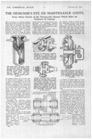
The pistons are made from a special alloy of aluminium, and the gudgeon pins are secured from end movement and consequent scoring of the cylinder walls by means of the now commonly adopted wire spring ring. The connecting rods are of Duralumin and are fitted with two bolts only, the firm having found that two sto_ut bolts are more reliable than four slender ones. Bronze shells lined with white metal are used for the big-end bearings, and a chamfer is relied upon to distribute the oil rather than the more common oil ways. The oil is fed by pressure to all the crank bearings. Shims are fitted which separate both the outer parts as well as the bearings.
Great care is taken to prevent any possibility of a stoppage of the oil circulation as, in the later models, the oil passes through no fewer than five strainers, each in turn having a finer mesh. This may appear to be an unnecessary refinement, but to those who have had experience in the filtering of engine oil it will appear to be a very wise provision. The filtering of engine oil is by no means an easy matter as, unless the mesh of the strainer be fine enough to arrest small particles of foreign matter, it is useless. On the other hand, if it be fine enough, it soon becomes clogged. The present arrangement is de
signed to form an -71 efficient strainer
which will not clog.
Over the WheLe area of the engine sump is a coarse strainer which catches the larger particles; owing to its large area it is not likely to become clogged. The oil, after having passed this first strainer, is directed through a second strainer slightly finer, and after this it passes to the centre of the three cylindrical strainers, shown in the illustration, where it percolates through each of the gauzes in turn, the gauzes being arranged with the finest on the outside. The construction of the cylinders of gauze is worthy of special note, as it will be seen that they are free to slide up the central nozzle through which the oil enters, being only in contact with the chamber through their own weight, all of them having open bases. Should these gauze cylinders become clogged through neglect to clean them, a pressure will be generated through the oil not being permitted to escape through the gauze ; the effect of this will be that the cylinder will rise and allow the oil to pass between the bottom of the cylinder and the outer chamber.. All three gauze cylinders are arranged in the same way.
Tile difficulty of oil filtering will he appreciated • when we point out that some users have had so many failures arising from stoppage of oil how through clogged filters that they have cut out all attempts at filtering and allow, the oil to flow unfiltered. Although this is known to be wrong, it is considered bet& than taking the risk of passing it through filters of ordinary construction.
Engine governors have practically fallen into disuse for home work, but there are still cases where they are required, as, for instance, where natives have to be . relied upon as drivers in hot climates. The governor fitted to the Thornycroft engines is of very simple construction, consisting of a gear-driven disc, inside which is a sliding cone, pressed home by means of a spiral spring. Between the cone and the body of the disc several bails are placed, which by centrifugal force are thrown towards the outside of the cone, thus forcing it away from the fiat surface. This movement causes , the rings on the shaft of the cone to impart a slight rotary movement to. the pinion with which they mesh,. and this rotary movement is transmitted to a throttle by means of
a flexible shaft.,, The. whole arrangement is totally : enclosed, so cannot be tampered with, nor can it be altered in its effect wiThout the use of new parts.
Provision is made for the fitting of a dynamo and magneto running tandemwise, or a magneto only, the bed for both being the same.
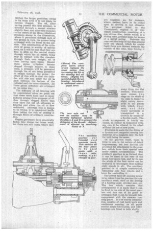
Of the gearbox itself, there is little to note in the nature of detail improvement, but two devices are provided for attachment to the gearbox, which have their special uses under certain circumstances. The auxiliary gearbox is so formed that it can be fixed to the rear of the usual four-speed box, and by its use the whole of the four ratios can be employed in two ranges, thus making eight speeds in all; The auxiliary gearbox is of simple construction, containing only four wheels and a lever for controlling it.
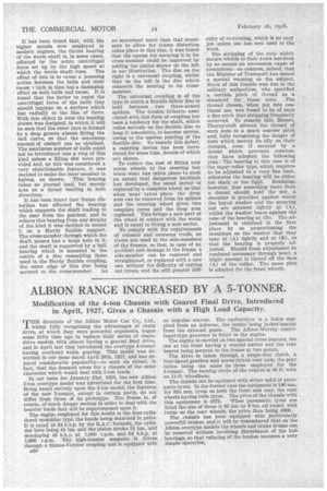
The power take-off enables power to be taken from the gearbox for any auxiliary work, such as the driving of a hauling gear, circular saw, etc. The box which contains this arrangement is so made that it can. be fixed to the side of the usual gearbox and has one of its gears so arranged that it can be brought into engagement with the constant run-. ning gears. It is of sturdy construction, capable of real hard work and continuous running, as all parts receive ample lubrication, and roller bearings are fitted to both shafts. It has been found that, with the higher speeds now employed in modern engines, the thrust bearing of the worm shaft is, in some cases, affected by the acute centrifugal force set up by the high speed at which the worm shaft runs. The effect of this is to cause a jamming action between the balls and their races, vhich in time has a damaging effect on both balls and races. It is found that the better to resist the centrifugal force of the balls they should impinge on a surface which lies radially to the line of force. With this object in view the bearing shown was designed, in which it will be seen that the outer race is formed by a deep groove almost fitting the ball curve, so that the rnaximum amount of contact can be obtained. The maximum number of balls could not be introduced into a ring of this kind unless a filling slot were provided and, as this was considered a very objectionable feature, it was decided to make the inner member in halves, as shown. This bearing takes no journal load, but merely acts as a thrust bearing in both directions.
It has been found that frame distortion has affected the bearing which supports the shaft leading to the rear from the gearbox, and to relieve this bearing from any strains of the kind it was decided to mount is on a Hardy flexible support. The cross-member through which the shaft passes has a large hole in it, and the shaft is supported by a ball bearing which is mounted in the centre of a disc resembling those used in the Hardy flexible coupling, the outer edge of this disc being secured to the cross-member. As no movement more than that necessary to allow for frame distortion takes place in this disc, it was found that the means for securing it to its cross-member could be improved by adding the plates shown on the left in our illustration. The disc on the right is a universal coupling, whilst that on the left is the disc which connects the bearing to its cross member.
The universal coupling is of the type in which a flexible fabric disc is held between two three-armed spiders. The trouble hitherto associated with this form of coupling has been a tendency for the shaft, which relies entirely on the flexible disc to keep it concentric, to become untrue, owing to the uneven yielding of the flexible disc. To remedy this defect, a centring device has been intro(bleed for some time, details of which are shown.
To reduce the cost of fitting new worm wheels to the steering box when wear has taken place to such an extent that dangerous backlash has developed, the usual sector is replaced by a complete wheel, so that when wear takes place the drop arm can be removed from its splines and the steering wheel given two complete turns and the drop arm replaced. This brings a new part of the wheel in contact with the worm and is equal to fitting a new sector.
To comply with the requirements of colonial and overseas trade, no rivets are used in the side-members of the frames, so that, in case of an accident and damage to the frame, a side-member can be removed and straightened, or replaced with a new one, without the difficulty of cutting out rivets, and the still greater diffi
culty of re-riveting, which is no easy job unless one has men used to the work.
The stripping of the nuts which secure wheels to their axles has been by no means an uncommon cause of breakdown—so common, indeed, that the Minister of Transport has issued a special warning on the subject. Much of this trouble was due to the military authorities, who specified a certain pitch of thread as a standard for these nuts. The thread chosen, when put into continual use, was found to be of such a fine pitch that stripping frequently occurred. To remedy this, Messrs. Thornycroft altered the thread of such nuts to a much coarser pitch
• and, fully recognizing the danger of nuts which merely lie idly on their threads, even if secured by a detent which prevents rotation, they have adopted the following plan : The bearing in this case is of the taper-roller type, which requires to be adjusted to a very fine limit, otherwise the bearing will be either too slack or too tight. Realizing, however, that something more than a detent should hold the nut, a shoulder is provided against which the keyed washer and the securing nut are screwed tightly at (A), whilst the washer bears against the cone of the bearing at (B). The adjustment is obtained in the first place by so proportioning the shoulders on the washer that they bear at (A) tightly and at (B), so that the bearing is properly adjusted. Should fresh adjustment be rendered necessary through wear, a slight amount is turned off the face (A) of the collar. The same plan Is adopted for the front wheels.