


PATENTS SUMMARIZED.
Page 22
If you've noticed an error in this article please click here to report it so we can fix it.
Combined Pivot and Ackermann Steering.
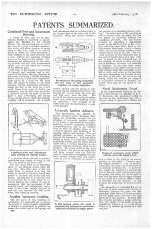
A design of front axle for an agricultural tractor is described in specification No. 112,350, by the Parrett Tsactor Co., the principal aim of which has been to evolve a suitable construction which will allow, freedom of movement of the axle itself in a vertical plane, as when one wheel snrmounts a large obstacle or the other descends into a hole, without any resultant twisting strain on the frame of the vehicle. Furthermore, the arrangement of the steering is such that any such displacement of the axle will not affect the working of the steering gear.
The flame of the chassis is constructed of channel steel sections, and is narrowed at the front, the two channels at this point embracing a beilike structure. Below this box, a horizontal longitudinal shaft serves as a pivot for the front axle, the design of which, in all other respects, follows Ackermann• principles. Inside the box is the pivot for a bell crank lever' both arms of which are horizontal. One of them—that one which is directed towards the front of the vehiele.—is bent downwards, and carries at its end the pin to which the steering coupling rod is attached. As a result
of its peculiar shape, the pin in question
approachea. very closely to being in line with the pivot of the front axle. For this reason little or no disturbing effect on the steering occurs when the axle tilts. The other arm of the bell crank lever is coupled to a king rod which is. carried to the rear,' being eupe ported at the back end in the rear axle casing. At this end it is screwed, and
surroimded by a out which is revolved through the medium of gear in accordance with the movement of the steering wheel, and Consequently, movement of the latter propels the rod to and fro, and operates the bell crank lever, thus effecting steering. •
Another Agrimotor Coupling.
The two parts of this coupling for agrirnoters are cortnected by a spring, the tension of which is easily adjustable A ehatkle is maintained in position between the slotted end of the spring bolt 1352 and cam-shaped slots in a frame which is an'integral pastel the ether end of the Cempling. When the tension exceeds a The tension of the spring connecting the two parts of this agrimotor coupling are easily adjustable.
sertairt amount and the spring is cornpresser) beyond predetermined limits the shackle pin travels along the cam slot and falls away from the bolt. The action of this device can readily be understood by a study of the drawing, which we reproduce. The inventor is D. Shankland and the specification is numbered 112,579.
Automatic Ignition Advance.
This specification, No. 102,951, by Societ4 ..knonyme pour l'Eclairage Eleetrique des Vehicules, concerns the application of automatic ignition control to all kinds of generators of electricity, including batteries, magnetos, dynamos, dynamo-magnetos, and so on, whether they be used for ignition alone, or for combined ignition and lighting, or for ignition, lighting and starting. The centrifugal governor, • as usual, forms the basis of the mechanism. Although fairly simple in itself, it is somewhat complex to describe briefly, and thar&der should follow what is written hereafter in conjunction with the drawing, which we reproduce. The lower shaft is the "main driving shaft, that part to the right hand end being integral with the armature shaft of the-dynamo or magneto, the lefthand portion coming from the engine. Both, it will be observed, ars keyed to
one portion of a peculiarly-shaped coupling. The other part of the coupling is free to revolve upon the shaft, and the two halves are connected through the centrifugal governor. The last named operates by imparting a differential action to the left-hand half of the coupling, and this takes effect, both on the high-tension distributor, which is shown above, and on the contact breaker, which appears below and to the left. The upward extension of the horizontal arm of the contact breaker bears on a cam. This cam ie keyed to the left-hand half of the coupling, to which we have referred, and is therefore advanced and retarded in company. At the same time, under the influence of the groove shown in the main driving shaft, this cam slides to the left or right, and owing to the fact that the cams themselves are broader at one end than at the other, the actual period during which the contacts are engaged is maintained constant in duration, Co matter what may be, the speed of the motor.
Novel Atcelerator Pedal.
In the improvement which is the subject of this patent, No, 112,485, by I. N. C. Icoressios, the accelerator pedal is provided at the right-hand side with a trigger, which is operated by sliding the feet a little -to the right of its normal position on the pedal. Pressure upon the trigger releases it from its ratchet, whereupon the pedal can be operated as in ordinary circumstances. If, however, the trigger be released by moving the foot to the left, while atill pressing upon' the pedal, the latter will be brought to rest with the pawl of the trigger engaged in one tooth of a vertical ratchet which is .proyided for the purpose. In this position the pedal may be used as a foot
rest. , •
An alternative is suggested for use in the case of such commercial vehicles as habitually traverse the same road day after day, when there will he one position for the pedal most convenient for long stretehee g that if.eareey. To meet this, the inventor provides a single-tooth ratchet,' the height of the tooth being adjustable by fitting it in a vertical slot to which it is secured by means of a bolt
and nut. •