


Patents Completed.
Page 28
If you've noticed an error in this article please click here to report it so we can fix it.
SUSPENSION SPRING.—Brown and Another.—No. 4,820, dated 27th February, 1906.—The spring (Al of a traction engine is mounted above the axle and its free ends bear against wedge-shaped blocks (D) beneath the engine or boiler.
The blocks are shown in the drawing as lying beneath brackets (B) secured to the horn-plates (C) of the boiler, and the blocks are connected together by a rod (E) having, at one end, a right-hand screw thread and, at the other end, a leftband screw thread. By rotating the rod (E) in one direction, or the other, the springs can be immediately adjusted by, thus, increasing or decreasing the distance between them and the brackets (B).
STEAM WAGON.—Nayler and Others. —No. 603, dated 9th January, 1906.—The horn plates of the boiler, according to this invention, are extended rearwardly and outwardly, as at a, and their free ends are
secured to the frame member (b). The sides of the frame member are parallel and, in addition to being connected to the free ends of the horn plates, they are, further, connected to the boiler ends of the same by means of brackets (c). Yet another connection may be made between the horn plates and the frame by pins (e) ; these can also be used to carry, some of the transmission gear wheels,
ROAD WHEELS.—The New ArrolJohnston Car Co., Ltd., and Another.— No. 1,248, dated 17th January, 1906.— For vehicles having a fixed axle (Ai, the brake drum (C) is provided with a sleeve (B1 and can be slid on to the axle, where it is retained in place by an end-thrust collar and nut. Over the sleeve (B) the wheel (D) is slid into place and is secured to the brake-drum by bolts (H).
LIQUID-FUEL BURN ER.—Meldrum. —No. 8,975, dated 14th April, 1906.—The liquid-fuel enters by one or more conduits (A), whence it passes to a vaporising chamber (B). Within this chamber is a downwardly-directed tube (C), whose lower end (t.'1) is reduced, and enters the outlet of a vapour reservoir (D). The end (Cl) is smaller than the outlet, so that an annular orifice is provided by this means, and a shoulder (C2) on the tube serves as a spreader for the flame. The chamber (D) is carried on a screwthreaded stem (131), so that the size of the outlet orifice can be regulated by turning the chamber and thus advancing or withdrawing it relatively to the shoulder (C2) on the tube (C). By raising the chamber so high that the shoulder (C2) is seated upon the orifice, the outlet may be entirely closed.
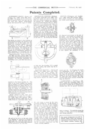
M.A.GNETIC CLUTCH. — Martin and Another.—No. 3,663, dated 14th February, 1906.—The clutch member (B), which is fast on the driving shaft (A), has an annular recess in its face wherein is mounted a channelled ring (D). The ring extends beyond the clutch member
a, and enters a recess in the corresponding member (C). In the channel of the ring two coils (E, El) are mounted, and these are connected with a suitable source of electric supply through a switch, which is connected in such manner with the coils that the current may pass through the two coils in "series,' or In 'parallel" but in opposite directions. The coil (E) lies within the member (B), and the coil (El) within the member (C), and when the current passes through both, in series, the two clutch members will be forcibly drawn together, but when it is passed through the coils, in opposite directions, the clutch parts will be oppositely magnetised, and the clutch instantly released. CLUTCH.—Wellington and Another. —No. 1,460, dated 19th January, 1906.— This clutch comprise an inner member (A), which carries spring-controlled dogs 1)) disposed transversely to the axis of the clutch. The member (A) rotates with the driving shaft (B), and slides into the
corresponding clutch part (C). This clutch part has an interior enlarged portion (Cl), which bears against the free end of the dogs (D) so that, as the part (A) enters the part (C), these dogs are moved outwardly, and frictionally engage the clutch part (C). Pivoted to the outer part (C) are spring-controlled arms (F) carrying rollers (f), which are adapted to bear against the periphery of the clutch part (A). On bringing the clutch into engagement, the part (C) is first ' started by the frictional engagement of the dogs (D) therewith, and, then, the rollers (f) of the spring-controlled levers (F) drop into place between the dogs, and the ends of the recesses wherein the dogs are disposed.
LUBRICATION — Sp yk e r. — No. 25,171, dated 8th November, 1906.—The oil is pumped from the oil-bath and conducted by a conduit (D) to nozzles (I) so situated that the oil sprayed therefrom falls in a stream. Through this stream the cranks, or other parts to be lubricated, pass during operation.