


WAYS AND MEANS.
Page 65
If you've noticed an error in this article please click here to report it so we can fix it.
Useful Contributions from Our Driver and Mechanic Readers.
An Improvized Screwing. Die. AN ingenious tip is sent us by " J.T.S.," of Patricroft, which may be of use to many who have to tackle screw threads for which they have no It was necessary to remove the wheels of a Tilling-Stevens lorry to attend to the brakes. In doing so the fine thread on the axle sleeve became damaged so that the ring nut would only just start but would not screw home. He tried filing the thread, but, as one would conclude, this did net make a satisfactory clearance of the damaged thread. He found that he had a chaser which fitted the thread, so he replaced the wheel, removed two of the studs which hold the hub cap and made a clamp plate with which he held the chaser tightly against the face of the hub. By setting the chaser so that its teeth pressed well into the threads, he was able to use the wheel as a die, and after three cuts he was able to screw the ring nut on as well as if he Lad used a proper die. It was fortunate for him that the wheel was a fairly good fit on its sleeve, or he might not have been so succeesfuL
This appears to us to be a tip that is well worth remembering.
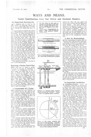
Repairing a Broken Petrol Pipe. THE best way to repair a broken petrol or oil pipe is, according to "D.D.I.," of Cleckheaton, to turn a brass collar and solder this on to the pipe, as shown in the upper drawing of the two on this subject. In many cases a lathe is not available and the following method is quite good : take some copper wire, about 16-gauge, and flatten out same; wind this tightly and evenly over both ends of the pipe for a total distance of about 3 ins., as in the lower drawing. Run solder thoroughly round this wire and the pipe will be quite serviceable.
A Countershaft for a Lathe.
THE following tip is by " B.L.R.," of Llaullyfni, and for the sake of simplicity we have slightly altered his design, making it necessary to use only two striking levers instead of three, as shown in his original sketch. Our correspondent has not called attention to the fact that in arrangements of this kind it is necessary that the forks which control the belts should act only on the on-going part of the belt, and not on the off-coming part, so we have made this clear in the upper part of the sketch.
The two-speed reverse countershaft illustrated was devised and built for a small screw-cutting lathe which was used for a great variety of work, from tingling hard steel to high-speed wood turning, thus requiring a wide range of speeds.
Two forward speeds and one reverse were provided, and • as the lathe was furnished with back gears the arrangement gave 12 speeds for normal use and six for the reverse, the speeds ranging from 30 r.p.m. to 1,000 r.p.m.
The two levers were arranged conveniently near the head of -the lathe, one behind the other, the low speed and reverse lever in front and the high-speed levers behind. One lever should be made of iron and one of wood, or they should be of different shapes to prevent mistakes in handling. Tight and loose pulleys without clutches were used, those on the countershaft being of the same size of iron, whilst the lineshaft pulleys were of different diameters and were of the straight-face wooden type.
A Hint for Reassembling.
IN the reassembling of engines that are
several years obi and have undergone a thorough overhaul it is often noticeable that there is an appreciable amount of lag in the timing of the valves. "A.R.W.," of Glasgow, has noticed this, and says that in some cases he has found as much as 3 ins, or even 4 ins, of travel of the flywheel before the exhaust valves close, as compared with the timing when the engine was new. Apart from lag due to wear on the valve stem, there is wear on the cam itself and on the roller. All wear tends not only to make all-operations late, but a shortening of the frilly opened period takes place. "A.R.W." says that if he sets his exhaust valve so that it opens at the original time he finds that it closes too soon, which causes a great loss of power. To remedy this defect he has adopted the plan of setting his timing so that the error due to wear takes place at the beginning of the exhaust stroke and not at the finish. His sketch shows the original timing and the reduction of the open period, also the timing he has adopted, which, he tells us, is the best way to set an engine that has suffered much from wear due to long service.
An Improvised Accelerator.
A CORRESPONDENT, "GA,," of Leicester, writes that he was driving a Dennis lorry with a 5-ton load when the taper pin which connects the foot accelerator broke and, naturally, the engine would only tick over as there are no hand controls on the steering column. It was dark and inclined to be foggy, and the load had to be delivered that night, so he devised some means to get it to its destination. Looking in his toolkit he found that there was a roll of copper wire, which he fastened on to the arm of the butterfly valve which operates in the carburetter and passed the end of the wise through a hole in the dash. "G.A." then cut a piece of wood from the hedge and fastened the copper wire on to that. 40 was then able to control the engine and in this way was able to deliver the load. As the lorry was urgently required it was necessary to use it during the next day in the same condition, and it was not until the following night that a new pin was fitted. The only trouble to be overcome was that the improvised hand control was not rigid, which meant that to change gear, operate the carburetter and steer was somewhat difficult. It was not like driving a Commer Car or Albion lorry, both of which have hand controls fitted.