


MAKING BEST USE OF THE FORD.
Page 53
If you've noticed an error in this article please click here to report it so we can fix it.
Valuable Advice on Every Phase of Ford Transport which will Appeal to the Owner, Driver, and Repairer.
471.—Overhauling the Light-van Axle.
The overhauling of the axle of the tight van is quite a straightforward job, anti providing that one or two special features are taken into consideration it can be carried out in a short time.
Assuming that the unit as a whole has been removed from the chassis, take out the six drive-shaft-housing bolts and remove the two castle nuts from the front ends of the radius rods. Unscrewing the radius-rod locknuts will now draw the housing out of the axle casing.
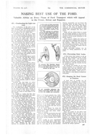
Before removing the wheels, pack up the casing or mount it in a stand. Then, by end pressure on the wheels, ascertain the amount of end play on the axle-shaft thrust washers.
After stripping and cleaning, examine the housings. Incidentally, the latter shnnld be given a rough paraffin bath and than thoroughly and quickly cleaned by the aid of a hose pipe.
The inner roller-bearing sleeves rarely require renewal, but the felt washers may have to be replaced. The outer sleeves, however, are often badly worn and. if so, must be renewed.
The easiest method to remove a sleeve is to take out the grease cup and to tap the sleeve round in the housing with a ptineh until the sleeve covers the grease hole. Then, if a centre punch be inserted into the hole, the sleeve can be tapped out of the casing a sufficient distenet, to enable it to be withdrawn by using, a pair of pliers, with which it should be given a twisting movement tending to compress it. The sleeves are in pairs, so that it is possible to insert the wrong one, the changing over of whielt would probably result in damaging it severely.
Examine the ring gear, or crown wheel, by which name it is more commonly known, for chipped teeth, tightness and security of the studs holding it tn the differential casing. Fractures of the ring gear have been traced to excessive wear of the thrust washers allowing the studs to foul ridges in the axle casing.
Be careful to replace the fibre disc between the differential-shaft ends when ree,ssembling the differential gear. If wear be apparent in the bearing tracks of the shaft they must be renewed, particularly if it be present at the wheel ends, as these bearings support the weight of the vehicle and satisfactory results cannot be obtained if up-and-down play be present, for, apart from the possibility of leakage of grease, there will be too little clearance between the lower brake' shoes and the drums ; consequently, play will result in the brakes being permanently on.
Ilaving previously ascertained the amount of end play and renewed the thrust washers, grease the inner roller bearings and reassemble' them without the outer rings. By assembling the axle dry, the freeness or otherwise can be ascertained. No adjustment other than that afforded by the thrust washers is provided for the crown wheel, so it found perfectly free, without excessive end play, it can be passed as being correct. A little thick oil can then be poured into the differential gear and Ih. of soft grease into the casing. Filling the casing completely with grease is not to be commended; on the contrary, it is merely adding friction, and much of the grease will ooze out on to the brake drums.
If the bevel pinion be worn or chipped, it should be renewed, as it is a hard-working unit and must, consequently, be sonnd.
Examine also the bevel-pinion key and renew if worn. After removal of the castle nuts, knock out the shaft through the pinion, neng a hammer and a block of wood.
Little trouble is now experienced with the drive-shaft sleeve, roller bearing and thrust races, but examine them end fit new ones if at all doubtful. During reassembly, do not forget the universal joint, as this, being out of sight, is often out of mind, and labour costs in the case of renewal after assembly are out of proportion to those before this operation has been completed.
Slack off the casing bolts to permit the drive-shaft housing to bed properly. In later models the housing bolts are not pinned or wired, so pay attention to the spring washers.
After removal, tighten the radius-rod nuts, but before pinning them cheek the axle shafts to see if they are central in the housing. This can best be done when the engine is running. If they are not central, readjust the radius rods to counteract the trouble.
Much axle-shaft leakage can be traced to wrong adjustment at this point.
472.—Preventing Body Leaks.
A Ford driver has written to tell us that he has experienced much trouble through damp coils. He. discovered that the wet was getting through to them owing to the body warping between the windscreen and the bonnet, leaving an actual opening.
To remedy the trouble, he cut some strips of leather to a wedge shape and pressed these into the opening, afterwards trimming them level and varnishing them with shellac. This proved a most effective cure, which is completely watertight.
473.—Keeping the Head Gasket in Position.
A good deal of trouble can be occasioned in assembling the cylinder head, both with regard to fitting of the cap screws and, later, in the running of the engine, if there be any misplacement of the gasket while the head is being assembled. The gasket itself may be damaged in trying to force in the cap screws, and in one case which was observed a slight overlap past the side of the cylinder wail was responsible for an ominous knock due to the piston head striking the overlapping portion.
One awkward point in assembling the bead is to be found in the rear cap screws, which must be inserted before the head is laid on the top of the cylinder block. They have, however, an inconvenient habit of dropping through and fouling-the gasket. They should, therefore, be partially inserted only and the heads tied together by a piece of string, the tension of which will prevent them moving.
Place the gasket on the block with pistons numbers one and four on the top dead centre. Use a couple of cap screws, from which the heads have been removed, as guides, down which the casting can be passed ; this will ensure ease in refitting and freedom from mishap. If fiats be filed on the sides of the truncated cap screws, these Can be removed by using a spanner.